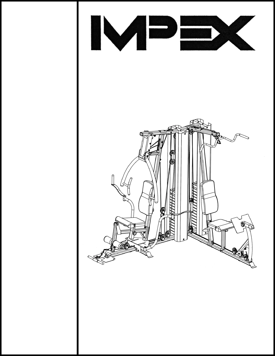
NOTE: Please read all instructions carefully before using this product Table of Contents Safety Notice Hardware Pack Assembly Instruction Parts List ® MARCY PLATINUM CORNER GYM MP-4500 Resistance Chart Warranty Ordering Parts Model MP-4500 Retain This Manual for Reference 10-25-06 OWNER'S MANUAL IMPEX® INC. 14777 DON JULIAN RD., CITY OF INDUSTRY, CA 91746 Tel: (800) 999-8899 Fax: (626) 961-9966 www.impex-fitness.com info@impex-fitness.
TABLE OF CONTENTS BEFORE YOU BEGIN...................................................................................... IMPORTANT SAFETY NOTICES..................................................................... HARDWARE PACK……….....…....................................................................... ASSEMBLY INSTRUCTIONS...............................................................….......... PARTS LIST…………………………………………………………….……….……. RESISTANCE CHART………………………………………………………………. WARRANTY...............
IMPORTANT SAFETY NOTICE PRECAUTIONS This exercise machine is built for optimum safety. However, certain precautions apply whenever you operate a piece of exercise equipment. Be sure to read the entire manual before you assemble or operate your machine. In particular, note the following safety precautions: 1. Keep children and pets away from the machine at all times. DO NOT leave children unattended in the same room with the machine. 2. Only one person at a time should use the same station. 3.
WARNING LABEL REPLACEMENT The warning labels shown here have been placed on the Left Base Frame and Left Upper Frame. If the labels are missing or illegible, please call customer service at 1-800-888-8899 for replacements. Apply the labels in location shown.
HARDWARE PACK NOTE: The following parts are not drawn to scale. Please use your own ruler or scale to measure the size.
HARDWARE PACK NOTE: The following parts are not drawn to scale. Please use your own ruler or scale to measure the size.
HARDWARE PACK NOTE: The following parts are not drawn to scale. Please use your own ruler or scale to measure the size.
ASSEMBLY INSTRUCTION Tools Required Assembling the Machine: Two Adjustable Wrenches and Allen Wrenches NOTE: It is strongly recommended two or people assembling this machine to avoid possible injury. STEP 1 (See Diagram 1) A.) Place the Right Base Frame (#31) on a flat surface. Make sure there is enough space around to assemble the machine. B.) Insert four Guide Rods (#16) into the holes on the Right Base Frame. Secure each Guide Rod from bottom with a M10 x ¾” Allen Bolt (#95) and Ø ¾” Washer (#100). C.
DIAGRAM 1 8
STEP 2 (See Diagram 2) A.) Attach the Right Upper Frame (#1) onto the Right Vertical Frame (#4). Secure it with two M10 x 2 ¾” Carriage Bolts (#98), one 4 ¾” x 2 ¾” Bracket (#25), two Ø ¾” Washers (#100), and two M10 Aircraft Nuts (#102). Do not tighten the Nuts and Bolts yet. B.) Attach the Right Upper Frame to the four Guide Rods (#16). Secure it to each Guide Rod with one M10 x ¾” Allen Bolt (#95) and Ø ¾” Washer (#100). C.) Securely tighten the Nuts and Bolts previously installed. D.
STEP 3 (See Diagram 3) A.) Attach the Front Press Base (#2) to the Right Upper Frame (#1). Secure it with one 6 ¾” Front Press Base Axle (#29), two Ø 1 ¼” x Ø 3/8” Washers (#70), and two M10 Aircraft Nuts (#102). Do not over tighten the Nuts; make sure the Base is able to swivel. B.) Attach the Front Press (#3) to the Front Press Base (#2). Secure it with one 7 5/8” Front Press Axle (#30), two Ø 1 ¼” x Ø 3/8” Washers (#70), and two M10 Aircraft Nuts (#102).
DIAGRAM 3 11
STEP 4 (See Diagram 4) A.) Attach the Seat Pad (#42) to the Seat Post (#6). Secure it with two M8 x 1 5/8” Allen Bolts (#85) and Ø 5/8” Washers (#101). B.) Insert the Seat Post into the opening on the Right Seat Support (#7). Secure it with a Lock Knob (#73) to lock the Seat Post at desired height. C.) Insert the Foam Tube (#23) halfway through the hole on the Leg Developer (#8). Push two Foam Rolls (#58) onto the Tube from both ends. Plug a Foam Roll End Cap (#59) into each end of the Tube.
STEP 5 (See Diagram 5) A.) Attach the Right Butterfly (#10) onto the axle on the Butterfly Base (#13). B.) Insert the Butterfly Handle (#9) into the pivot on the Right Butterfly. Secure it with one M10 x ¾” Allen Bolt (#95) and Ø 1 ¼” x Ø 3/8” Washer (#70) from the bottom. Do not over tighten the Bolt; make sure the handle is able to swivel. C.) Repeat Procedure A & B above to install the Left Butterfly (#11).
STEP 6 (See Diagram 6) A.) Do not tighten all Nuts and Bolts in this Step until instructed to do so. B.) Attach the Left Vertical Frame (#33) onto the Left Base Frame (#32). Secure it with two M10 x 2 ¾” Carriage Bolts (#98), one 4 ¾” x 2 ¾” Bracket (#25), two Ø ¾” Washers (#100), and two M10 Aircraft Nuts (#102). C.) Attach the Left Base Frame (#32) to the Right Base Frame (#31).
STEP 7 (See Diagram 7) A.) Attach the Left Upper Frame (#34) onto the Left Vertical Frame (33). Secure it with two M10 x 2 ¾” Carriage Bolts (#98), one 4 ¾” x 2 ¾” Bracket (#25), two Ø ¾” Washers (#100), and two M10 Aircraft Nuts (#102). Do not tighten the Nuts and Bolts yet. B.) Attach the rear of Left Upper Frame to the Right Upper Frame (#1). Secure it with two M10 x 3 ½” Carriage Bolts (#99), one 4 ½” x 2” Bracket (#26), two Ø ¾” Washers (#100), and two M10 Aircraft Nuts (#102). C.
STEP 8 (See Diagram 8) A.) Attach the Left Seat Support (#35) onto the Left Base Frame (#32). Secure it with one M10 x 3 ½” Carriage Bolt (#99), Ø ¾” Washer (#100), and M10 Aircraft Nut (#102). B.) Attach the Left Seat Support to the Left Vertical Frame (#33). Secure it with two M10 x 2 ¾” Carriage Bolts (#98), one 4 ¾” x 2 ¾” Bracket (#25), two Ø ¾” Washers (#100), and two M10 Aircraft Nuts (#102). C.) Attach the Right & Left Handle (#37& 38) to the Left Seat Support from each side.
STEP 9 (See Diagram 9) A.) Attach the Leg Press Frame (#36) to the bracket on the Left Base Frame (#32). Secure it with an Axle (#15), two M10 x ¾” Allen Bolts (#95), and two Ø ¾” Washers (#100). B.) Insert the Leg Press Adjustment Frame (#40) into the Leg Press Frame. Thread a Lock Knob (#73) into the Leg Press Frame to obtain the desired leg press exercise position. C.) Attach the Leg Press Plate (#39) to the Leg Press Adjustment Frame.
STEP 10 (See Diagram 10 & Front Press Cable Loop Diagram) A.) Attach one end of the 140” Front Press Cable (#48) to the bracket underneath the Right Upper Frame (#1). Secure it with one M10 x 1” Allen Bolt (#94), two Ø ¾” Washers (#100), and one M10 Aircraft Nut (#102). B.) Draw the Cable to the opening on the Front Press Base (#2). Attach a Pulley (#67) to the upper opening. Secure it with one M10 x 6 ¼” Allen Bolt (#88), two Ø ¾” Washers (#100), and one M10 Aircraft Nut (#102). C.
DIAGRAM 10 19
Front Press Cable Loop Diagram 20
STEP 11 (See Diagram 11 & Lower Cable Loop Diagram) A.) Attach the 157” Lower Cable (#46) to the lower opening on the Leg Developer (#8). Attach a Pulley (#67) to the opening. Secure it with one M10 x 2 5/8” Allen Bolt (#92), two Ø 7/8” x 5/8” Pulley Bushings (#56), and one M10 Aircraft Nut (#102). B.) Draw the Cable underneath the Pulley to the open bracket on the Right Base Frame (#31).
DIAGRAM 11 22
Lower Cable Loop Diagram 23
STEP 12 (See Diagram 12 & Butterfly Cable Loop Diagram) A.) Clip one end of the 96” Butterfly Cable (#45) to the open slot on the Right Butterfly (#10). B.) Draw the Cable to the open bracket on the right side of the Right Vertical Frame (#4). Attach a Small Pulley (#68) to the bracket. C.) Secure it with one M10 x 1 ¾” Allen Bolt (#93), two Ø ¾” Washers (#100), and one M10 Aircraft Nut (#102). D.) Draw the Cable around the Small Pulley to the right open bracket on the Right Base Frame (#31).
25
Butterfly Cable Loop Diagram 26
STEP 13 (See Diagram 13 and Upper Cable Loop Diagram) A.) Attach the 130’” Upper Cable (#44) to the front opening on the Left Upper Frame (#34). Attach a Pulley (#67) to the opening. Secure it with one M10 x 3 ½” Allen Bolt (#90), two Ø 7/8” x 1” Pulley Bushings (#53), and one M10 Aircraft Nut (#102). B.) Draw the Cable over the Pulley along the Left Upper Frame towards the back of the machine. Make sure the Ball Stopper on the Cable is underneath the Left Upper Frame. C.
DIAGRAM 13 28
Upper Cable Loop Diagram 29
STEP 14 (See Diagram 14) A.) Attach the end of the 103” Leg Press Cable (#47) to the bracket on the Leg Press Frame (#36). Secure it with a M10 x 1 ¾” Allen Bolt (#94), two Ø ¾” Washers (#100), and one M10 Aircraft Nut (#102). B.) Draw the Cable to the first open bracket on the front of Left Base Frame (#32). C.) Install a Pulley (#67) to the bracket with one M10 x 1 ¾” Allen Bolt (#93), two Ø ¾” Washers (#100), and one M10 Aircraft Nut (#102). D.
DIAGRAM 14 31
Leg Press Cable Loop Diagram 32
STEP 15 (See Diagram 15) A.) Attach four Weight Stack Covers (#41) to the Right Upper Frame (#1) and Right Base Frame (#31). B.) Secure each Weight Stack Cover with two M10 x 5/8” Allen Bolts (#96) and Ø ¾” Washers (#100).
PARTS LIST KEY NO.
MP-4500 WEIGHT RESISTANCE CHART WEIGHT PLATE Station 1 2 3 4 5 6 7 Low Pulley 22 33 44 55 66 77 88 Lat Pull 30 40 50 60 70 80 90 Leg Developer 26 38 50 62 74 86 98 Leg Press 36 60 84 108 132 156 180 Front Press 20 34 48 62 76 90 104 Butterfly 10 16 22 28 34 40 46 WEIGHT PLATE Station 8 9 10 11 12 13 14 Low Pulley 99 110 121 132 143 154 165 Lat Pull 100 110 120 130 140 150 160 Butterfly 110 122 134 146 158 170 182 Leg Pre
® IMPEX INC. LIMITED WARRANTY ® IMPEX Inc. ("IMPEX ") warrants this product to be free from defects in workmanship and material, under normal use and service conditions, for a period of two years on the Frame from the date of purchase. This warranty extends only to the original purchaser. IMPEX's obligation under this Warranty is limited to replacing or repairing, at IMPEX's option. All returns must be pre-authorized by IMPEX.