NOTE: Please read all instructions carefully before using this product Table of Contents Safety Notice Hardware Identifier Assembly Instruction Marcy Classic Home Gym MCH-1510 Parts List Resistance Chart Warranty Ordering Parts Model MCH-1510 Retain This Manual for Reference 5-9-07 OWNER'S MANUAL IMPEX INC. 14777 DON JULIAN RD., CITY OF INDUSTRY, CA 91746 Tel: (800) 999-8899 Fax: (626) 961-9966 www.impex-fitness.com info@impex-fitness.
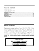
TABLE OF CONTENTS BEFORE YOU BEGIN....................................................................................……….. 1 IMPORTANT SAFETY NOTICE...................................................................……….. 2 HARDWARE PACK……….....….....................................................................……….. 4 ASSEMBLY INSTRUCTIONS.........................................................................……….. 7 PARTS LIST………………………………………………………………………………….. 19 RESISTANCE CHART…………....................
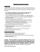
IMPORTANT SAFETY NOTICE PRECAUTIONS This exercise machine is built for optimum safety. However, certain precautions apply whenever you operate a piece of exercise equipment. Be sure to read the entire manual before you assemble or operate your machine. In particular, note the following safety precautions: 1. Keep children and pets away from the machine at all times. DO NOT leave children unattended in the same room with the machine. 2. Only one person at a time should use the machine. 3.
WARNING LABEL REPLACEMENT The warning labels shown here have been placed on the Rear Base and Upper Frame. If the labels are missing or illegible, please call customer service at 1-800-888-8899 for replacements. Apply the labels in the location shown.
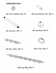
HARDWARE PACK 4
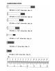
HARDWARE PACK 5
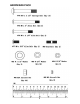
HARDWARE PACK 6
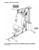
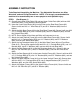
ASSEMBLY INSTRUCTION Tools Required Assembling the Machine: Two Adjustable Wrenches, two Allen Wrenches, and one Philips Screwdriver. NOTE: It is strongly recommended this machine to be assembled by two or more people to avoid possible injury. STEP 1 (See Diagram 1) A.) Connect two Lower Guide Rods (23) and two Upper Guide Rods (#24) with two M10 Stud Bolts (#80). Firmly thread the Rods together. B.) Insert the Lower Guide Rods (#23) into the holes on the Rear Base Frame (#2).
DIAGRAM 1 8
STEP 2 (See Diagram 2) A.) Slide two Ø2 ½” x 1” Rubber Bumpers (#65) onto the Guide Rods. B.) Slide 9 Weight Plates (#33) onto the Guide Rods. Make sure the groove on the Weight Plates all facing the back of the machine and downward. Insert the Selector Rod (#17) through the center hole on the Weight Plates. C.) Slide the Selector Stem (#32) onto the Guide Rods. D.) Slide the Ring on the String onto the Selector Rod (#17). E.) Attach the Upper Frame (#4) onto the two Guide Rods.
DIAGRAM 2 10
STEP 3 (See Diagram 3) A.) Attach the Front Press Base (#11) to the Upper Frame (#4). Secure it with one Long Axle (#46), two Ø ¾” Washers (#83), and two M10 Aircraft Nuts (#85). B.) Attach the Right Butterfly (#6) to the Front Press Base (#11). Secure it with one Ø 1 ½” Washer (#82), one M6 x 1 ¼” Allen Bolt (#78), Lock Ring (#41), and M6 Aircraft Nut (#86). C.) Slide a Butterfly Foam Roll (#62) onto the Right Butterfly arm. Attach the Right Front Press Handle (#13) to the Right Butterfly.
STEP 4 (See Diagram 4) A.) Attach the Leg Developer (#7) to the bracket on the Leg Developer Holder (#1). Secure it with a Leg Developer Axle (#47), two M10 x 5/8” Allen Bolts (#74), and two Ø ¾” Washers (#83). B.) Insert two Foam Roll Tubes (#28) halfway through the holes on the Leg Developer and Leg Developer Holder. Push four Foam Rolls (#61) onto the Tubes from both ends. Plug four Foam Roll End Caps (#60) into the ends. C.) Place the Seat (#38) onto the Seat Support (#16).
CABLE LOOP DIAGRAM 13
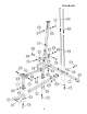
STEP 5 (See Diagram 5 & Cable Loop Diagram) A.) Attach the 142” Upper Cable (#35) to the opening at the front of the Upper Frame (#4). Note: The Ball Stopper on the cable should be underneath the Frame. B.) Attach a Pulley (#63) to the opening. Secure it with one M10 x 2 3/8” Allen Bolt (#71), two Pulley Bushings (#50), and one M10 Aircraft Nut (#85). C.) Draw the Cable towards the back of the machine to the opening on the Upper Frame. Repeat the Procedure B above to install another Pulley. D.
DIAGRAM 5 15
STEP 6 (See Diagram 6 & Cable Loop Diagram) A.) Attach one end of the 119” Butterfly Cable (#37) to the hook on the Right Butterfly (#6). B.) Draw the Cable to the right Swivel Pulley Bracket (#21). C.) Attach a Pulley to the bracket. Secure it with one M10 x 1 ¾” Allen Bolt (#72), two Ø ¾” Washers (#83), and one M10 Aircraft Nut (#85). D.) Draw the Cable around the Pulley then downward. Attach the Cable to a Crossed Double Floating Pulley Bracket (#20). Install another Pulley.
STEP 7 (See Diagram 7 & Cable Loop Diagram) A.) Attach the 128” Lower Cable (#36) to the open bracket on the bottom of the Leg Developer (#7). B.) Attach a Pulley to the bracket. Secure it with one M10 x 1 ¾” Allen Bolt (#72), two Ø ¾” Washers (#83), and one M10 Aircraft Nut (#85). C.) Draw the Cable underneath the Pulley to the opening on the Leg Developer Holder (#1). Attach a Pulley to the opening.
DIAGRAM 7 18
PARTS LIST KEY NO.
20
IMPEX INC. LIMITED WARRANTY IMPEX Inc. ("IMPEX") warrants this product to be free from defects in workmanship and material, under normal use and service conditions, for a period of two years on the Frame from the date of purchase. This warranty extends only to the original purchaser. IMPEX's obligation under this Warranty is limited to replacing or repairing, at IMPEX's option. All returns must be pre-authorized by IMPEX.