NOTE: Please read all instructions carefully before using this product Table of Contents Safety Notice Hardware Pack Assembly Instruction MARCY DIAMOND ELITE WEIGHT BENCH MD-2080 Parts List Warranty Ordering Parts Model MD 2080 Retain This Manual for Reference 08-04-09 OWNER'S MANUAL IMPEX® INC. 2801 S. Towne Ave, Pomona, CA 91766 Tel: (800) 999-8899 Fax: (626) 961-9966 www.impex-fitness.com info@impex-fitness.
TABLE OF CONTENTS BEFORE YOU BEGIN...................................................................................... IMPORTANT SAFETY NOTICE....................................................................... HARDWARE PACK ……….....…....................................................................... ASSEMBLY INSTRUCTIONS........................................................................... EXPLODED DIAGRAM.........................................................................……….
IMPORTANT SAFETY NOTICE PRECAUTIONS This exercise machine is built for optimum safety. However, certain precautions apply whenever you operate a piece of exercise equipment. Be sure to read the entire manual before you assemble or operate your machine. In particular, note the following safety precautions: 1. Keep children and pets away from the machine at all times. DO NOT leave children unattended in the same room with the machine. 2. Only one person at a time should use the machine. 3.
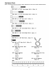
WRANING LABEL PLACEMENT The warning label shown here have been placed on the Cross Brace. If the label is missing or illegible, please call customer service at 1-800-888-8899 for replacements. Apply the label in the location shown.
Hardware Pack NOTE: The following parts are not drawn to scale. Please use your own ruler or scale to measure the size.
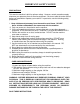
ASSEMBLY INSTRUCTION Tools Required for Assembling the Machine: Two Adjustable Wrenches. NOTE: It is strongly recommended that two or more people assemble this machine to avoid possible injury. STEP 1 (See Diagram 1) A.) Do not tighten Nuts and Bolts until instructed to do so. B.) Connect the two Upright Beams (#1) by a Cross Brace (#2) in the mid-span. C.
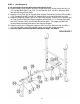
STEP 2 (See Diagram 2) A.) Do not tighten Nuts and Bolts until instructed to do so. B.) Attach the Main Seat Support (#3) to the Cross Brace (#2). Secure it with two M10 x 2 1/8” Carriage Bolts (#24), one 4 3/8” x 3 3/8” Bracket (#12), two Ø ¾” Washers (#33), and two M10 Aircraft Nuts (#35). C.) Attach the Front Post (#5) to the Main Seat Support. Secure the first hole with one M8 x 1 5/8” Carriage Bolt (#25), one Ø 5/8” Washer (#32), and one M8 Aircraft Nut (#34). D.
STEP 3 (See Diagram 3) A.) Attach the side-holes on the two Backrest Supports (#8) to the pivot on the Main Seat Support (#3). Place the other end of the Backrest Supports rest against the Backrest Adjustment Bar (#6). B.) Attach the Backrest Board (#11) to the Backrest Supports. Secure it with four M6 x 1 3/8” Hex Bolts (#28) and four Ø ½” Washers (#31). C.) Place the Seat Pad (#10) onto the Main Seat Support (#3). Secure it with four M6 x 5/8” Hex Bolts (#29) and four Ø ½” Washers (#31).
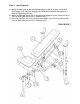
STEP 4 (See Diagram 4) A.) Attach the Leg Developer (#9) to the open bracket on the Front Post (#5). Secure it with one M10 x 2 3/8” Hex Bolt (#27), one Ø ¾” Washer (#33), and one M10 Aircraft Nut (#35). B.) Insert two Foam Tubes (#7) half way through the holes on the Leg Developer. C.) Push four Foam Rolls (#17) onto the Foam Tubes. D.) Attach a Spring Clip (#19) to the weight post on Leg Developer.
9
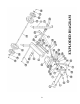
PARTS LIST KEY NO.
® IMPEX INC. LIMITED WARRANTY ® IMPEX Inc. ("IMPEX ") warrants this product to be free from defects in workmanship and material, under normal use and service conditions, for a period of two years on the Frame from the date of purchase. This warranty extends only to the original purchaser. IMPEX's obligation under this Warranty is limited to replacing or repairing, at IMPEX's option. All returns must be pre-authorized by IMPEX.