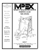
NOTE: Please read all instructions carefully before using this product Table of Contents Safety Notice Hardware Identifier MARCY DIAMOND ELITE SMITH CAGE MD-MXM6 Assembly Instruction Parts List Warranty Ordering Parts Model MD-MXM6 Retain This Manual for Reference 08-3-06 OWNER'S MANUAL IMPEX® 14777 DON JULIAN RD., CITY OF INDUSTRY, CA 91746 Tel: (800) 999-8899 Fax: (626) 961-9966 www.impex-fitness.com info@impex-fitness.
TABLE OF CONTENTS BEFORE YOU BEGIN...................................................................................... IMPORTANT SAFETY NOTICES..................................................................... HARDWARE PACK….......…..........................................………………………. ASSEMBLY INSTRUCTIONS...........................................……………………. EXPLODED DIAGRAM…………………………………………………………….. PARTS LIST………..……………………………………………………………….. WARRANTY........................................................
IMPORTANT SAFETY NOTICE PRECAUTIONS This exercise machine is built for optimum safety. However, certain precautions apply whenever you operate a piece of exercise equipment. Be sure to read the entire manual before you assemble or operate your machine. In particular, note the following safety precautions: 1. Keep children and pets away from the machine at all times. DO NOT leave children unattended in the same room with the machine. 2. Only one person at a time should use the machine. 3.
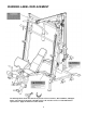
WARNING LABEL REPLACEMENT The warning labels shown here have been placed on the Cross Brace, Rear Stabilizer, and Upper Frame. If the labels are missing or illegible, please call customer service at 1-800-888-8899 for replacements. Apply the labels in location shown.
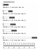
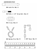
HARDEWARE PACK 4
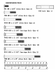
HARDEWARE PACK 5
HARDEWARE PACK 6
HARDEWARE PACK 7
ASSEMBLY INSTRUCTION Tools Required Assembling the Machine: Two Adjustable Wrenches and Allen Wrenches. NOTE: It is strongly recommended two or more people assembling this machine to avoid possible injury. STEP 1 (See Diagram 1) A.) NOTE: Do not tighten the Nuts and Bolts until instructed to do so. B.) Connect the Left & Right Base Frames (#26 & #27) by a Cross Brace (#36) in the midspan.
DIAGRAM 1 9
STEP 2 (See Diagram 2) A.) Attach the Rear Vertical Beam (#38) onto the Cross Brace (#36). Attach the Weight Glide Post (#34) to the Rear Vertical Beam and Cross Brace. Attach the Foot Plate (#115) to the Cross Brace. Align the holes and secure them with two M10 x 2 ¾” Carriage Bolts (#103), ∅ ¾” Washers (#89), and M10 Aircraft Nuts (#106). B.) Slide the Sliding Weight Post (#45) onto the Weight Glide Post (#34). C.
DIAGRAM2 11
STEP 3 (See Diagram 3) A.) Attach the Butterfly Base (#39) and Butterfly Pulley Bracket (#44) to the Rear Vertical Beam (#38). Align the holes and secure them with two M10 x 2 ½” Carriage Bolts (#102), ∅ ¾” Washers (#89), and M10 Aircraft Nuts (#106). B.) Insert the axle on the Right Butterfly (#41) through the hole on the Butterfly Base. Secure it with one Lock Ring (#80), M6 x 1 ¼” Allen Screw (#107), and M6 Aircraft Nut (#108). C.) Push a Butterfly Arm Pad (#58) onto the Right Butterfly. D.
STEP 4 (See Diagram 4) A.) Note: Help of another person is strongly recommended for this step. Place the Weight Lifting Sleeve (#48) in between the two Safety Stop Frames (#32). Align the holes and insert the Weight Bar (#49) into the Safety Stop Frame from one end through the Weight Lifting Sleeve to the other Safety Stop Frame on the opposite end. Center the bar and secure it to each Safety Stop Frame with two M8 x 3/8” Allen Bolts (#110) on each end. B.
CABLE LOOP DIAGRAM 14
STEP 5 (See Diagram 5 & Cable Loop Diagram) A.) Attach a 124” Cable (#60) to the front opening on the Upper Frame (#37). Attach a Pulley (#81) to the opening. Secure it with one M10 x 2 1/8” Allen Bolt (#94), two Ø 1 1/8” Bushings (#86), and one M10 Aircraft Nut (#106). Make sure the ball stopper on the Cable is underneath the Upper Frame. B.) Draw the Cable over the Pulley along the Upper Frame to the opening on the rear of Upper Frame. Attach a Pulley to the opening.
DIAGRAM 5 16
STEP 6 (See Diagram 6 & Cable Loop Diagram) A.) Attach one end of the 79” Butterfly Cable (#61) to the clip on the Left Butterfly (#40). Draw the Cable to the left Butterfly Pulley Bracket (#44). B.) Attach a Pulley (#81) to the Bracket. Secure it with one M10 x 1 ¾” Allen Bolt (#93), two ∅ ¾” Washers (#89), and one M10 Aircraft Nut (#106). C.) Draw the Cable around the Pulley then downward. Attach the Cable to a Single Floating Pulley Bracket (#47). Install a Pulley to the Bracket.
STEP 7 (See Diagram 7 & Cable Loop Diagram) A.) Attach one 124” Cable (#60) to the lower opening on the Rear Vertical Beam (#38). Attach a Pulley to the opening. Secure it with M10 x 2 3/8” Allen Bolt (#95), two Ø 1” Bushings (#85), and one M10 Aircraft Nut (#106). B.) Draw the Cable underneath the Pulley to the open bracket on the Weight Glide Post (#34). Attach a Pulley to the bracket. Secure it with one M10 x 1 ¾” Allen Bolt (#93), two ∅ ¾” Washers (#89), and one M10 Aircraft Nut (#106). C.
STEP 8 (See Diagram 8) A.) Attach the Front Post (#3) to the Front Stabilizer (#17). B.) Secure it with three M10 x 5/8” Allen Bolts (#90) and ∅ ¾” Washers (#89).
STEP 9 (See Diagram 9) A.) Attach the Main Seat Support (#1) to the Rear Stabilizer (#4). Secure it with two M10 x 2 3/8” Carriage Bolts (#100), one 5 1/8” x 2 3/8” Bracket (#21), two Ø ¾” Washers (#89), and two M10 Aircraft Nuts (#106). B.) Attach the Wheel (#14) to the Rear Stabilizer. Secure it with one M8 x 5 1/8” Allen Bolt (#98), two Ø5/8” Washers (#88), and one M8 Aircraft Nut (#109). C.) Place the Main Seat Support (#1) onto the Front Post (#3).
STEP-10 (See Diagram 10) A.) Attach the Leg Developer Holder (#2) to the Main Seat Support (#1). Secure it with one M10 x 5/8” Allen Bolt (#90) and Ø ¾” Washer (#89) from the top, two M10 x 3 ¾” Carriage Bolts (#101), two Ø ¾” Washers (#89), and two M10 Aircraft Nuts (#106) from the side. B.) Attach the Leg Developer (#12) to the Leg Developer Holder (#2). Secure it with one Axle (#18), two M10 x 5/8” Allen Bolts (#90), and two ∅ ¾” Washers (#89). C.
STEP-11 (See Diagram 11) A.) Insert two ؽ” Bushings (#113) into the holes on the Seat Bracket (#5) and align the holes to the pivot on the Main Seat Support (#1). B.) Attach the two Backrest Supports (#10) to the Seat Bracket and align the holes. Secure them with a M10 x 7 ¼” Allen Bolt (#97), two Ø ¾” Washers (#89), and one M10 Aircraft Nut (#106). Do not over tighten the Nut and Bolt. Make sure the Backrest Supports are able to swivel. C.
STEP-12 (See Diagram 12) A.) Place the Seat Pad (#8) onto the Seat Bracket (#5). Secure it with four M8 x 1 5/8” Allen Bolts (#99) and Ø5/8” Washers (#88). B.) Attach the Bench Backrest Board (#9) to the Backrest Supports (#10). Secure it with four M8 x 1 5/8” Allen Bolts (#99) and Ø5/8” Washers (#88). C.) Attach the Arm Curl Pad (#11) to the Arm Curl Stand (#6). Secure it with two M8 x 5/8” Allen Bolts (#91) and Ø 5/8” Washers (#88).
STEP-13 (See Diagram 13) A.) Insert three Foam Tubes (#16) halfway through the holes on Leg Developer Holder (#2) and Leg Developer (#12). B.) Push six Foam Rolls (#23) onto the Tubes from both ends. C.) Push six Foam Roll End Caps (#72) into the ends. D.) Attach the Arm Curl Handle (#19) to the bracket on the Leg Developer and secure it with a Lock Pin (#20). Remove the Arm Curl Handle when doing Leg Developer exercises.
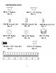
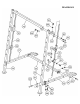
SMITH MACHINE EXPLODED DIAGRAM 25
26
PARTS LIST KEY NO.
® IMPEX LIMITED WARRANTY ® IMPEX warrants this product to be free from defects in workmanship and material, under normal use and service conditions, for a period of two years on the Frame from the date of purchase. This warranty extends only to the original purchaser. IMPEX's obligation under this Warranty is limited to replacing or repairing, at IMPEX's option. All returns must be pre-authorized by IMPEX. Pre-authorization may be obtained by calling IMPEX Customer Service Department at 1-800-999-8899.