NOTE: Please read all instructions carefully before using this product Table of Contents Safety Notice Hardware Pack Assembly Instruction Parts List MARCY ® Magnetic-Resistance Upright Bike ME-708 Warranty Ordering Parts Model ME-708 Retain This Manual for Reference 07-02-09 OWNER'S MANUAL IMPEX® INC. 14777 DON JULIAN RD., CITY OF INDUSTRY, CA 91746 Tel: (800) 999-8899 Fax: (626) 961-9966 www.impex-fitness.com info@impex-fitness.
TABLE OF CONTENTS BEFORE YOU BEGIN...................................................................................…. IMPORTANT SAFETY NOTICES..................................................................…. HARDWARE PACK……….....…....................................................................…. ASSEMBLY INSTRUCTIONS........................................................................…. EXPLODED DIAGRAM………………………………………………………………. PARTS LIST..........................................................
IMPORTANT SAFETY NOTICE PRECAUTIONS This exercise machine is built for optimum safety. However, certain precautions apply whenever you operate a piece of exercise equipment. Be sure to read the entire manual before you assemble or operate your machine. In particular, note the following safety precautions: 1. Keep children and pets away from the machine at all times. DO NOT leave children unattended in the same room with the machine. 2. Only one person at a time should use the machine. 3.
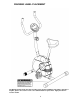
WARNING LABEL PLACEMENT The Warning Label shown here has been placed on the Rear Stabilizer. If the label is missing or illegible, please call customer service at 1-800-999-8899 for replacement. Apply the label in location shown.
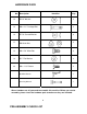
HARDWARE PACK No. Description Identifier Q’ty 12 Ø 5/8” Washer 2 15 M8 x 2 ½” Carriage Bolt 2 16 Ø 7/8” Curved Washer 6 17 M8 Acorn Nut 2 18 M8 x 5/8” Allen Bolt 8 19 Ø 1” Flat Washer 2 26 M8 x 1 1/8” Screw 2 #6 Allen Wrench 1 Crossing Wrench 1 Above hardware are all you need to assemble this machine. Before you start to assemble, please check the hardware pack to make sure they are included.
PART NO.
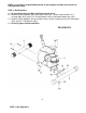
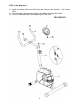
NOTE: It is strongly recommended that two or more people assemble this machine to avoid possible injury. STEP 1 (See Diagram1) A.) Do not tighten Nuts and Bolts until instructed to do so. B.) Attach the Front Stabilizer (#2) to the Main Frame (#1). Secure it with two M8 x 2 ½” Carriage Bolts (#15), two 7/8” Curved Washers (#16), and two M8 Acorn Nuts (#17). C.) Attach the Rear Stabilizer (#3) to the Main Frame. Secure it with three M8 x 5/8” Allen Bolts (#18), two Ø 1” Flat Washers (#19). D.
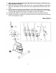
A.) Note: In order to hold the Front Post (#4) while connecting the cables and wires, extra help may be needed. B.) Attach the Front Post (#4) to the Main Frame (#1). Connect the Middle Computer Wire (#21) from the bottom of Front Post to the Lower Computer Wire (#22) from the main Fame. C.) Pull the tension connector from the Upper Tension Cable (#20) and slide in between the opening on the connector holder on the Lower Tension Cable (#23).
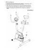
STEP 3 (See Diagram 3) A.) Attach the Handle (#5) to the Front Post (#4). Secure it with two M8 x 1 1/8” Screws (#26). B.) Connect Upper Computer Wire (#28) to the Middle Computer Wire (#21). C.) Insert the Computer (#6) into the opening on Front Post.
STEP 4 (See Diagram 4) A.) Remove the three Ø 5/8” Washers (#12), three Ø 3/8” Lock Washers (#13), and three M8 Aircraft Nuts (#14) from the Seat (#8). B.) Attach the Seat to the Seat Post (#7). Secure it with three Ø 5/8” Washers (#12), three Ø 3/8” Lock Washers (#13), and three M8 Aircraft Nuts (#14). C.) Insert the Seat Post into the opening on Main Frame (#1). Thread the Lock Knob (#11) through the hole on Seat Post to securely lock it at desired height.
STEP 5 (See Diagram 5) A.) Thread the Left Pedal (#9) counterclockwise into the Crank (#25). B.) Thread the Right Pedal (#10) clockwise into the Crank on the other side.
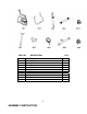
EXPLODED DIAGRAM 11
PARTS LIST KEY NO.
COMPUTER AUTO START / STOP When exercise starts, the monitor will automatically turn on and display the progress. When exercise stops, the monitor will automatically turn off after 8 minutes to save energy. Press “MODE” key, will automatically scan Time, Speed, Distance, Calories, and ODO for every 4 seconds. DISPLAY: Time Speed Distance Calories (ODO) Odometer Display the elapsed time. Max value is up to 99:59 Display the current speed in miles per hour. Display the distance traveled in Miles.
EXERCISE INSTRUCTIONS Using your MAGNETIC BIKE will provide you with several benefits, it will improve your physical fitness, tone muscle and in conjunction with calorie controlled diet help you lose weight. 1. The Warm Up Phase This stage helps get the blood flowing around the body and the muscles working properly. It will also reduce the risk of cramp and muscle injury. It is advisable to do a few stretching exercises as shown below.
3. The Cool Down Phase This stage is to let your Cardio-vascular System and muscles wind down. This is a repeat of the warm up exercise e.g. reduce your tempo, continue for approximately 5 minutes. The stretching exercises should now be repeated, again remembering not to force or jerk your muscles into the stretch. As you get fitter you may need to train longer and harder. It is advisable to train at least three times a week, and if possible space your workouts evenly throughout the week.
® IMPEX INC. LIMITED WARRANTY ® IMPEX Inc. ("IMPEX ") warrants this product to be free from defects in workmanship and material, under normal use and service conditions, for a period of two years on the Frame from the date of purchase. This warranty extends only to the original purchaser. IMPEX's obligation under this Warranty is limited to replacing or repairing, at IMPEX's option. All returns must be pre-authorized by IMPEX.