NOTE: Please read all instructions carefully before using this product Table of Contents Safety Notice Hardware Pack Assembly Instruction MARCY® MWM 981 HOME GYM Parts List Resistance Chart Warranty Ordering Parts Model MWM-981 Retain This Manual for Reference 100322 OWNER'S MANUAL IMPEX® INC. 2801 S. Towne Ave., Pomona, CA 91766 Tel: (800) 999-8899 Fax: (626) 961-9966 www.impex-fitness.com info@impex-fitness.
TABLE OF CONTENTS BEFORE YOU BEGIN....................................................................................……….. 1 IMPORTANT SAFETY NOTICES...................................................................……….. 2 HARDWARE IDENTIFIER.....….....................................................................……….. 4 ASSEMBLY INSTRUCTIONS.........................................................................……….. 6 PARTS LIST…………………………………………………………………………………. 21 RESISTANCE CHART………….................
IMPORTANT SAFETY NOTICE PRECAUTIONS This exercise machine is built for optimum safety. However, certain precautions apply whenever you operate a piece of exercise equipment. Be sure to read the entire manual before you assemble or operate your machine. In particular, note the following safety precautions: 1. Keep children and pets away from the machine at all times. DO NOT leave children unattended in the same room with the machine. 2. Only one person at a time should use the machine. 3.
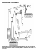
WARNING LABEL REPLACEMENT The warning labels shown here have been placed on the Rear Stabilizer and Upper Frame. If the labels are missing or illegible, please call customer service at 1-800-888-8899 for replacements. Apply the labels in the location shown.
HARDWARE PACK NOTE: The following parts are not drawn to scale. Please use your own ruler to measure the size.
HARDWARE PACK NOTE: The following parts are not drawn to scale. Please use your own ruler to measure the size.
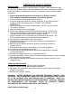
ASSEMBLY INSTRUCTION Tools Required for Assembling the Machine: Two Adjustable Wrenches and Allen Wrenches. NOTE: It is strongly recommended that this machine to be assembled by two or more people to avoid possible injury. STEP 1 (See Diagram 1) A.) Insert the two Guide Rods (#11) through Rubber Bumpers and into the holes on the Rear Stabilizer. Secure each Guide Rod with one M10 x 1” Allen Bolt (#64) and ¾” Washer (#73) from the bottom.
DIAGRAM 1 7
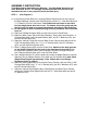
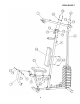
STEP 2 (See Diagram 2) A.) Attach the holes on the Upper Frame (#1) onto the Guide Rods (#11). Place the Upper Frame onto the Vertical Frame (#4). B.) Secure the Upper Frame to the Guide Rods with two M10 x 1” Allen Bolts (#64) and Ø ¾” Washers (#73). C.) Secure the Upper Frame to the Vertical Frame with two M10 x 2 3/8” Carriage Bolts (#58), one 1 ¾” x 4 ¾” Bracket (#18), two ¾” Washers (#73), and two M10 Aircraft Nuts (#70). D.
DIAGRAM 2 9
STEP 3 (See Diagram 3) A.) Attach the Front Press Base (#8) to the Upper Frame (#1). Secure it with one 8 ½” Front Press Axle (#19), two Ø 1” x Ø 5/8” Washers (#75), and two M10 Aircraft Nuts (#70). Do not over tighten the Nuts. B.) Insert the axle on the Left Butterfly (#9) through the open hole on Front Press Base from bottom. Secure it with one Ø 1” x Ø 5/8” Washers (#75) and one M10 Aircraft Nuts (#70). Do not over tighten the Nut. Push one large Foam Roll (#27) onto the Left Butterfly. C.
DIAGRAM 3 11
STEP 4 (See Diagram 4) A.) Insert the Front Press Handle (#12) into the hole on Right Butterfly (#10) and Left Butterfly (#9). Secure each Handle with one M8 x ¾” Allen Bolt (#61) and one Ø 5/8” Curved Washer (#76). B.) Insert 15 ¾” Long Foam Tube (#31) halfway through the hole on Seat Support (#5). Insert 15” Short Foam Tube (#22) halfway through the hole on Leg Developer (#7). C.) Push four Foam Rolls (#26) onto the Tubes from both ends of each Tube.
STEP 5 (See Diagram 5) A.) Attach one Swivel Pulley Bracket (#17) to the open bracket on the back of Vertical Frame (#4). Secure it with one M10 x 2 ½” Allen Bolt (#66), two Ø ¾” Washers (#73), and one M10 Aircraft Nut (#70). Do not over tighten the Nut and Bolt. Make sure the Swivel Pulley Bracket can swivel freely. B.) Repeat Procedure A to install the other Swivel Pulley Bracket on the other side.
STEP 6 (See Diagram 6 & Cable Loop Diagram) A.) Attach the 126” Upper Cable (#32) to the front open bracket under the Upper Frame (#1). B.) Attach a Pulley (#35) to the bracket. Secure it with one M10 x 1 ¾” Allen Bolt (#62), two Ø ¾” Washers (#73), and one M10 Aircraft Nut (#70). C.) Draw the Cable towards the back of the machine to the open bracket on Vertical Frame (#4). Repeat B to install a Pulley. D.) Draw the Cable around the Pulley then pull back to the opening on the Front Press Base (#8). E.
DIAGRAM 6 15
STEP 7 (See Diagram 7& Cable Loop Diagram) A.) Hook one end of the 98” Butterfly Cable (#34) to Right Butterfly (#10). B.) Draw the Cable towards the right open Swivel Pulley Bracket (#17). C.) Attach a Pulley (#35) to the bracket. Secure it with one M10 x 1 ¾” Allen Bolt (#62), two ¾” Washers (#73), and one M10 Aircraft Nut (#70). D.) Draw the Cable over the Pulley then pull downward. Attach the Cable to an Angled Double Floating Pulley Bracket (#16). Repeat Procedure C to install a Pulley.
STEP 8 (See Diagram 8 & Cable Loop Diagram) A.) Attach the 164” Lower Cable (#33) to the open bracket on the Base Frame (#3). B.) Attach a Pulley (#35) to the bracket. Secure it with one M10 x 1 ¾” Allen Bolt (#62), two ¾” Washers (#73), and one M10 Aircraft Nut (#70). C.) Draw the Cable underneath the Pulley then pull upward towards the Double Floating Pulley Brackets (#13) installed in Step-6. D.) Attach a Pulley to the selected hole on the Brackets.
DIAGRAM 8 18
STEP 9 (See Diagram 9) A.) Attach Lat Bar (#14) to the Upper Cable (#32) with two Hooks (#53) and one 15-link Chain (#54) when doing Lat Pull exercises. B.) Attach Shiver Bar (#15) to the Lower Cable (#33) use the two Hooks (#53) and the 15-link Chain (#33) from Lat Bar when doing Arm Curl exercises C.) Replace Shiver Bar with the Ankle Strap (#52) or Single Handle (#78) to the Lower Cable for various exercises. D.
Set up the Lock Combination A.) The combination is pre-set to 0-0-0 by the factory. B.) Turn the dials to 0-0-0 and aligned to the Combination Set Up Line. C.) Pull out the shackle and turn 1800. D.) Press down on the shackle. E.) Turn the dials (aligned to the Combination Set Up Line) to your desired combination. F.) Pull out the shackle and twist back to normal position and the combination are set. G.) Repeat Procedure C to F to re-set the combination.
PARTS LIST KEY NO.
MWM981 WEIGHT RESISTANCE CHART Weight Plate 1 2 3 4 5 6 7 8 9 10 11 Leg Developer 30 40 50 60 70 80 90 100 101 102 103 Front Press 31 44 57 70 83 96 109 122 135 148 161 Butterfly 15 20 25 30 35 40 45 50 55 60 65 Note: Each plate weights 10 lbs. Numbers are approximate. Actual weights may vary. Values for Butterfly are for each arm.
® IMPEX INC. LIMITED WARRANTY ® IMPEX Inc. ("IMPEX ") warrants this product to be free from defects in workmanship and material, under normal use and service conditions, for a period of two years on the Frame from the date of purchase. This warranty extends only to the original purchaser. IMPEX's obligation under this Warranty is limited to replacing or repairing, at IMPEX's option. All returns must be pre-authorized by IMPEX.