
Home Gym User Manual

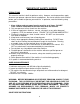
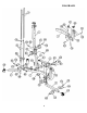

STEP 2 (See Diagram 2)
A.) Slide nine Weight Plates (#42) onto the Guide Rods. Make sure the groove on the
Weight Plates all facing the back of the machine and downward. Insert the
Selector Rod (#23) through the center hole on the Weight Plates.
B.) Slide the Selector Stem (#41) onto the Guide Rods. Make sure the center groove
faces downward.
C.) Slide the Ring on the String of the Selector Pin (#34) onto the Selector Rod.
D.) Attach the Upper Frame (#10) onto the two Guide Rods. Secure them with two
M10 x 1” Allen Bolts (#88) and Ø ¾” Washers (#95).
E.) Place the Upper Frame (#10) onto the Upper Vertical Frame (#7). Secure them
with two M10 x 2 ¾” Carriage Bolts (#80), one 4 ¾” Bracket (#28), two Ø ¾”
Washers (#95), and two M10 Aircraft Nuts (#92).
F.) Securely tighten all Nuts and Bolts previously installed.
G.) Cover the Weight Plates with the Weight Stack Cover (#53). Secure it with three
M10 x 5/8” Allen Bolts (#89) and Ø ¾” Washers (#95).
H.) Attach the Front Press Support Frame (#12) to the Upper Vertical Frame (#7).
Secure it with one M10 x 2 ½” Allen Bolt (#84) and Ø ¾” Washer (#95).
I.) Attach the Butterfly Pulley Bracket (#13) to the back of the Upper Vertical Frame
(#7). Secure it with one M10 x 2 ½” Carriage Bolt (#81), Ø ¾” Washer (#95), and
M10 Aircraft Nut (#92).
J.) Attach two Swivel Pulley Brackets (#14) to the Butterfly Pulley Bracket (#13).
Secure each Swivel Pulley Bracket with one M10 x 2 ½” Allen Bolt (#84), two Ø
¾” Washers (#95), and one M10 Aircraft Nut (#92).
K.) Attach the Leg Developer (#4) to the Leg Developer Holder (#19). Secure it with
one M12 x 3 1/8” Allen Bolt (#90), two Ø 1” Washers (#94), and one M12 Aircraft
Nut (#93).
L.) Insert the Arm Curl Stand (#20) into the Leg Developer Holder (#19). Secure the
height with the Lock Knob.
9