® MAQ 20 Industrial Data Acquisition and Control System Configuration Software Tool User Manual
MAQ®20 Configuration Software Tool User Manual ® MAQ 20 Industrial Data Acquisition and Control System Configuration Software Tool User Manual MA1037 Rev. B – May 2012 © 2012 Dataforth Corporation. All Rights Reserved. ISO9001:2008-Registered QMS The information in this manual has been checked carefully and is believed to be accurate; however, Dataforth assumes no responsibility for possible inaccuracies or omissions. Specifications are subject to change without notice.
MAQ®20 Configuration Software Tool User Manual Table of Contents 1.0 MAQ®20 Communication Setup 1.1 Quick Setup ................................................................................................................................... 1 1.2 MAQ 20 Communication Setup & Connection ........................................................................... 1 ® 2.0 MAQ®20 Configuration Software Tool Panel 2.1 Registration Tab .....................................................................
MAQ®20 Configuration Software Tool User Manual 7.3.2 Pulse / Frequency Counter with De-bounce Function ....................................................... 14 7.3.3 Waveform Measurement Function ..................................................................................... 14 7.3.4 Time Between Events Function ......................................................................................... 14 7.3.5 Frequency Generator Function ..............................................................
MAQ®20 Configuration Software Tool User Manual About Dataforth Corporation “Our passion at Dataforth Corporation is designing, manufacturing, and marketing the best possible signal conditioning, data acquisition, and data communication products. Our mission is to set new standards of product quality, performance, and customer service.
MAQ®20 Software Configuration User Guide 1.0 MAQ®20 Communication Setup 1.1 Quick Setup 1. Download the Configuration Software Tool from the Dataforth website, www.dataforth.com and follow the installation procedure. If the system will be used with a USB connection to the host PC, the USB Driver must be installed prior to connecting the system to the computer. Download the driver from www.dataforth.com and follow the installation instructions. ® 2.
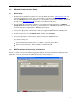
MAQ®20 Configuration Software Tool User Manual From the Communication pull-down menu, select Configure. The Communication Setup panel will appear giving the user the ability to configure the communication port, reference Figure 2. Figure 2: Communication Setup Panel If the system is connected via RS-232 or RS-485, ensure the RS-232, RS-485 radio button is selected. Select the appropriate Communication Port number from the Port # drop-down menu.
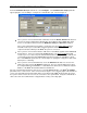
MAQ®20 Configuration Software Tool User Manual 2.0 MAQ®20 Configuration Software Tool Panel The File menu has a Print function which allows the user to send the system configuration details to a printer as well as save them to a text file located in the C:\Dataforth\MAQ20\MAQ20 Config SW Vx.x folder. The Log Configure function under the File menu allows the user to log data selected in the Module Comm panel to a text file. Features of the Module Comm tab are explained in Section 2.
MAQ®20 Configuration Software Tool User Manual Figure 4: Configuration Software Tool, Module Comm Tab 2.2 Module Data Panel: This tab allows the monitoring of up to 5 different registered modules or up to 5 different addresses spaces of the same module. First select the module to be monitored using the Module # drop down box, next select the address to be monitored from the Address drop down box, and last, select the number of addresses to be monitored using the Read Qty numeric up/down box.
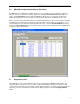
MAQ®20 Configuration Software Tool User Manual 3.0 Configuring the MAQ®20 Communications Module Figure 5: MAQ20-COMx Communications Module Configuration Panel 3.1 Communication Settings: This panel allows the Ethernet and Serial communications parameters of the MAQ20-COMx module to be changed. The factory default values for Ethernet communications are; IP Address 192.168.128.100, Subnet Mask 255.255.0.0.
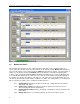
MAQ®20 Configuration Software Tool User Manual 4.0 Configuring the MAQ®20 Volt/Millivolt Input Modules Figure 6: MAQ20-VDN Voltage Input Module Configuration Panel To configure the module click on any cell in a row of the Main Registration Panel and then click the Configure Module button this will open the MAQ20 volt input configuration panel.
MAQ®20 Configuration Software Tool User Manual limits. When an alarm limit for a given channel is exceeded, the background color of the cell displaying data for that channel will change indicate which limit has been exceeded. 4.3 Alarm Configuration for Input Channels: This section is used to configure alarm settings for each channel. Alarm choices are High, Low, HighHigh and Low-Low. High / Low and High-High / Low-Low ranges have separate Dead Bands which can be specified.
MAQ®20 Configuration Software Tool User Manual 5.0 Configuring the MAQ®20 Thermocouple Input Module Figure 7: MAQ20-JTC Thermocouple Input Module Configuration Panel To configure the module click on any cell in a row of the Main Registration Panel and then click the Configure Module button this will open the MAQ20 Thermocouple Input Module. Four modules are offered to interface to five different thermocouple types; one for Type J, one for Type K, one for Type T and one for Types R and S. 5.
MAQ®20 Configuration Software Tool User Manual 5.3 Alarm Configuration for TC Input Channels: This section is used to configure alarm settings for each channel. Alarm choices are High, Low, HighHigh and Low-Low. High / Low and High-High / Low-Low ranges have separate Dead Bands which can be specified. Alarm limits must have the same units as the Analog Input Readings (Counts or Engineering Units). Enter the alarm limits and press the Set Alarm Settings button to write the values to the module.
MAQ®20 Configuration Software Tool User Manual 6.0 Configuring the MAQ®20 Voltage Output Module Figure 8: MAQ20-VO Voltage Output Module Configuration Panel To configure the module click on any cell in a row of the Main Registration Panel and then click the Configure Module button this will open the MAQ20 Voltage Output Module configuration panel. 6.1 Voltage Output and Range Values: Output Range settings can be set for the 8 isolated outputs on a channel-by-channel basis.
MAQ®20 Configuration Software Tool User Manual Preset data can be output to between 1 and n sequential channels up to a maximum of 8 channels. Use the Channels numeric up/down box in the Buffer Interval n Chans group box to enter the number of channels to write to, and press the Set button to send the selection to the module. Data will remain in module memory until the next power cycle. Press the Save button to store the settings in the module nonvolatile memory.
MAQ®20 Configuration Software Tool User Manual 7.0 Configure the MAQ®20 Discrete Input/Output Module Figure 9: MAQ20-DIO Discrete Input/Output Module Configuration Panel To configure the module click on any cell in a row of the Main Registration Panel and then click the Configure Module button this will open the MAQ20 Discrete Input/Output Module configuration panel. 7.1 Discrete I/O Configuration: The I/O channel display on the panel represents the fixed configuration of the module.
MAQ®20 Configuration Software Tool User Manual 7.2 Discrete I/O Special Function Alarms: The Discrete I/O Module can perform seven special functions. Some of these special functions use set pairs of channels. This area of the panel sets the alarm conditions for Discrete Input channels 5-6 and 78. 7.2.1 Inputs: Use this drop-down box to select the channels for which alarms will be set: Ch 56 or Ch 7-8. 7.2.2 Function: Select the function from the drop-down box.
MAQ®20 Configuration Software Tool User Manual 7.3 Special Function Panels: Special functions operate using preset channels associated with one of two Timers: Channels 0, 1, 5 and 6 are associated with Timer 0 and Channels 2, 3, 7 and 8 are associated with Timer 1. Each of the two timers can run any one of the seven special functions at any given time. The panel displays the special functions selected for each of the two timers.
MAQ®20 Configuration Software Tool User Manual Frequency 7.3.5 Frequency Generator Function Uses output channel 0 for Timer 0 and output channel 2 for Timer 1. Can generate a frequency between 1 and 10kHz Waveform will have a duty cycle of 50% 7.3.6 PWM Generator Function Uses output channel 0 and 1 for Timer 0 and output channel 2 and 3 for Timer 1. This function allows the user to generate a waveform up to 10kHz with a user defined duty cycle.
MAQ®20 Configuration Software Tool User Manual DATAFORTH WARRANTY Applying to Products Sold by Dataforth Corporation a. General. Dataforth Corporation (“Dataforth”) warrants that its products furnished under this Agreement will, at the time of delivery, be free from defects in material and workmanship and will conform to Dataforth's applicable specifications or, if appropriate, to buyer's specifications accepted in writing by Dataforth.
MAQ®20 Configuration Software Tool User Manual (4) DATAFORTH’S LIABILITY ARISING OUT OF THE PRODUCTION, SALE OR SUPPLY OF PRODUCTS OR THEIR USE OR DISPOSITION, WHETHER BASED UPON WARRANTY, CONTRACT, TORT OR OTHERWISE, SHALL NOT EXCEED THE GREATER OF EITHER US$1000.00 (ONE THOUSAND DOLLARS U.S.A. CURRENCY) OR THE ACTUAL PURCHASE PRICE PAID BY BUYER FOR DATAFORTH'S PRODUCTS. DATAFORTH'S LIABILITY FOR ANY CLAIM OF ANY KIND SHALL IN NO CASE EXCEED THE OBLIGATION OR LIABILITY SPECIFIED IN THIS WARRANTY. d.
MAQ®20 Configuration Software Tool User Manual _____________________________________________________________________________________________ Application Support Dataforth provides timely, high-quality product support. Call 1-800-444-7644 TOLL-FREE. Returns/Repair Policy All warranty and repair requests should be directed to the Dataforth Customer Service Department at (520) 741-1404. If a product return is required, request a Return Material Authorization (RMA) number.