ReDAQ® Shape Software for MAQ®20 User Manual MAQ®20 Industrial Data Acquisition and Control System ® ® ReDAQ Shape for MAQ 20 User Manual 1
ReDAQ® Shape Software for MAQ®20 User Manual ® ® ® MAQ 20 Industrial Data Acquisition and Control System ReDAQ Shape for MAQ 20 User Manual MA1038 Rev. B – May 2012 © 2012 Dataforth Corporation. All Rights Reserved. ISO9001:2008-Registered QMS The information in this manual has been checked carefully and is believed to be accurate; however, Dataforth assumes no responsibility for possible inaccuracies or omissions. Specifications are subject to change without notice.
ReDAQ® Shape Software for MAQ®20 User Manual ® MAQ 20 is a registered trademark of Dataforth Corporation. ® Windows is a registered trademarks of Microsoft Corporation. Measurement Studio™ and LabVIEW™ are trademarks of National Instruments Corporation. Table of Contents Introduction ................................................................................................................................................. 6 1.1 Overview ................................................................
ReDAQ® Shape Software for MAQ®20 User Manual 5.3.4 Discrete Waveform Graph Tool ................................................................................................ 41 5.3.5 Knob Tool ................................................................................................................................. 42 5.3.6 Meter Tool ................................................................................................................................ 43 5.3.7 Gauge Tool .................
ReDAQ® Shape Software for MAQ®20 User Manual About Dataforth Corporation “Our passion at Dataforth Corporation is designing, manufacturing, and marketing the best possible signal conditioning and data communication products. Our mission is setting new standards of product quality, performance, and customer service.
ReDAQ® Shape Software for MAQ®20 User Manual Introduction 1.1 Overview ® ® ReDAQ Shape Software for the MAQ 20 Industrial Data Acquisition and Control System is Dataforth’s out-of-the-box data acquisition software which provides the easiest and most efficient development tool to create, save, and open graphical user interface projects as well as to test, process, and analyze acquired data. It can also log data to the hard drive, and copy, and delete data at run time.
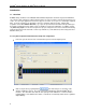
ReDAQ® Shape Software for MAQ®20 User Manual To create Present panels for application projects: ® Select Acquire panel for quick setup and click on the [Connect] button to connect to the MAQ 20 system as well as testing and acquisition of data. Select Analyze panel to allow data logging, real-time analysis, and data processing. Select Present panel to build and create custom graphical user interfaces. After selecting a Present panel, use Tools such as Switch, Scope, LED, etc. to build a project.
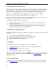
ReDAQ® Shape Software for MAQ®20 User Manual The following illustrates a Present panel project: 8
ReDAQ® Shape Software for MAQ®20 User Manual ® ® The ReDAQ Shape Software for MAQ 20 offers 18 different types of Tools for building applications: The Graph group contains: Chart Recorder Scope XY plot Discrete Waveform Graph The Knob group contains: 5 styles of Knobs The Meter group contains: 4 styles of Meters The Gauge group contains: 6 styles of Gauges The Tank group contains: 6 styles of Tanks The Slide group contains: 6 styles of Slides The Thermometer group contains: 6 styles of Thermometers The Nu
ReDAQ® Shape Software for MAQ®20 User Manual 1.2 Developer Version and User Version There are two versions of the software, Developer and User. The Developer version is fully functional ® with the capability of creating a project, configuring the Tools, and setting up the parameters of MAQ 20 COM and I/O modules. The User version can only run finished projects created using the Developer version and is for use in applications where a user does not have the ability to modify a project.
ReDAQ® Shape Software for MAQ®20 User Manual development, but will only run for 30 minutes. Order the License Unlock Code, part number MAQ20-940, from Dataforth Corporation to enable unlimited use. ® The License Unlock Code is tied to the serial number of the COM module of MAQ 20 Data Acquisition System being used.
ReDAQ® Shape Software for MAQ®20 User Manual The following documents are available from Modbus IDA ( www.modbus.org ): HU • • • UH Modbus Application Protocol Specification Modbus over Serial Line Specification & Implementation Guide Modbus Messaging on TCP/IP Implementation Guide The following Tools and documents are available from FieldTalk ( www.modbusdriver.
ReDAQ® Shape Software for MAQ®20 User Manual 2.2 Software Menus There are 5 main pull-down menus: File: • • • • • Open new project - Start a new project and reset Acquire, Analyze and Present panels to default settings Open existing project Save project - Save the project to a file .rsd. Each project also includes image files and text files in a separate folder titled Images. Save project for user only - Save the project to a User file .rsu.
ReDAQ® Shape Software for MAQ®20 User Manual 2.4 Panel – Select A given project can have one Acquire panel, one Analyze panel, and up to 20 Present panels. The Acquire and Analyze panels can be hidden or shown using the View pull down menu. The Present panels can be added, removed or renamed. 2.5 Status and Message Bar The status and message bar is located at the bottom of the main software panel. It includes 6 types of information.
ReDAQ® Shape Software for MAQ®20 User Manual Before an application can be run, the system must be configured using the Acquire panel. Enable each system connected: Default: System 1 - Enabled. System 2 to 10 - Disabled. Select the communication port for each system: Ethernet, USB or Serial IP Address: Default = 192.168.128.100. USB: Default = Port 1. Serial port name: COM1-COM20. Default = COM3. Serial port baud rate: 921600, 460800, 230400, 115200, 57600, 38400, 19200, 9600, 4800, 2400. Default = 115200.
ReDAQ® Shape Software for MAQ®20 User Manual NOTE WHEN USING USB COMMUNICATION TO MULTIPLE SYSTEMS: If multiple systems are connected using USB communications, the systems will be populated in the software in the order that they are powered up. For example, the first system powered up would be assigned as System 1 and the second as System 2.
ReDAQ® Shape Software for MAQ®20 User Manual Click on the [Save] button to save the changes. The system configuration is now stored in the COM module nonvolatile memory and I/O modules will be shown in the same slots for all subsequent power cycles. Setup COM Tab: Communication Parameters such as Slave ID, Serial Baud Rate, Parity, IP address and Subnet mask are modified using this panel. Click on the [Save New Settings] button to store changes in the COM module nonvolatile memory.
ReDAQ® Shape Software for MAQ®20 User Manual SD Memory card tab: This tab provides a simple interface to set up data logging parameters, check the memory card size and estimated remaining space, start/stop data logging, and verify logging. Enter the desired file name in the File Name text box. The filename must be a maximum of 7 characters, follow standard MS Windows naming convention, and have a ‘.txt’ extension. The default filename is ‘File1.txt’.
ReDAQ® Shape Software for MAQ®20 User Manual 3.3 Analog Input Modules The Analog Input Module configuration panel has three tabs [Setup, Scale Data and Control Loop/Alarm] that provide a simple interface to configure and collect data from analog input modules such as MAQ20MVDN, -VSN, -VDN, -ISN, -IDN, -RMS, -RTD31, -RTD41, -BRDGN, -JTC, -KTC, -TTC, -RSTC, etc.
ReDAQ® Shape Software for MAQ®20 User Manual Input Range can be set independently for each channel. Use the Input Range selection box to set the desired value. The data scale also automatically reset when the input range changed. Control Loop or Alarm Output function for a given analog input channel is configured by selecting the desired function from the selection box. Alarms can be Tracking or Latched with High, Low, High-Low, High-High, Low-Low, or High-High Low-Low limits.
ReDAQ® Shape Software for MAQ®20 User Manual ® The MAQ 20 analog input values have 12-bit resolution plus sign, which equates to a full scale range of -4095 to 4095 counts. This count range can be scaled to any engineering units on a per-channel basis. By default, the analog input channels are scaled to the selected input range. For example, if an input range of -5 to +5V is selected for a given channel, then collected data for that channel is automatically scaled to -5 and +5V.
ReDAQ® Shape Software for MAQ®20 User Manual 1. Select the Control Loop or Alarm Output mode for analog input channels in the Setup tab. 2. Configure the channel Control Loop or Alarm Output active state, Discrete Output and/or Analog Output mapped channel, Alarm Limits and Deadband parameters in the Control Loop / Alarm Output selection box. 3.
ReDAQ® Shape Software for MAQ®20 User Manual Setup tab: Each channel can have a unique User Tag Name. The system automatically assigns the default tag name when the system is first connected.
ReDAQ® Shape Software for MAQ®20 User Manual Data points must be comma delimited. The last character in a sequence indicates how the data is to be output. If the last value is the character ‘S’, the output scan will stop. If the last value is the character ‘R’, the output scan will loop back to the starting point and continue to run until stopped by the user. Output data format: Value 1, Value 2, Value 3,…,Value n, S Value 1, Value 2, Value 3,…,Value n, R Output the data sequence once, then stop.
ReDAQ® Shape Software for MAQ®20 User Manual Example: A voltage output module is configured for -10V to +10V output range Data in counts is written Channel 0 A data value of 0x0000 corresponds to an output of -10V. A data value of 0x0FFF corresponds to an output of +10V. To scale the -10 to +10V output range to a linear representation of a -100°C to +300°C output range, enter the data shown below: 3.
ReDAQ® Shape Software for MAQ®20 User Manual To change the tag name, enter the new name in the User Tag Name text box for the channel. References to this channel in other panels will use this tag name. The user can view discrete input data in the DIO Status data display boxes and write discrete output data by entering a value of 0 or 1 in the Output Data boxes.
ReDAQ® Shape Software for MAQ®20 User Manual Example 1: Frequency Generator: Select the Frequency Generator function in the Timer 1 block Enter the desired output frequency Set the Disarm/Arm/Enabled state to Arm Click the Start button.
ReDAQ® Shape Software for MAQ®20 User Manual 4.0 Test, Process, and Analyze Data in Analyze Panel 4.1 Analyze Panel ® The Analyze panel has four tabs to test, process, and analyze data from the MAQ 20 data acquisition system without any programming. View Raw Data View Analog Input Channels View Discrete DIO Channels Read / Write Modbus Registers Once communications with the system have been configured and established, the tools on the Analyze panel can be used at any time by pressing the Start button.
ReDAQ® Shape Software for MAQ®20 User Manual To save collected data to a file on the host computer, select ‘Enable save to file’ from the selection box. This will save raw data to a text file without units. Select ‘Enable save / unit’ if it is desired to have units on the collected data saved to the text file. Text file size is only limited by the host computer hard drive available space. The rate at which data is logged is set by the system sampling interval.
ReDAQ® Shape Software for MAQ®20 User Manual 4.3 View Analog Input Channels The View Analog Input Channels tab provides graphical views of acquired data. Seven different modes are available for optimal data display: Fixed AutoScaleLoose AutoScaleExact ScopeChart StripChart AutoScaleVisibleLoose AutoScaleVisibleExact Analog input channels displayed on the graph are enabled using the Channel Select checkboxes. X and Y axis limits can be set using the pull down boxes.
ReDAQ® Shape Software for MAQ®20 User Manual 4.4 View Discrete I/O Channels The View Discrete I/O Channels tab provides a graphical view of the data for the five discrete input channels on the MAQ20-DIOx module. Data can be displayed or hidden using the +/- box at the top left corner of the plot. The horizontal hash mark in the left hand legend represents the midscale value for each channel for determination of channel low/high state.
ReDAQ® Shape Software for MAQ®20 User Manual 4.5 Read / Write Modbus Registers The Read / Write Modbus Registers tab provides a simple interface to directly read and write any Modbus register in the system. Through this interface, the user can setup, configure, test, and operate the ® MAQ 20 data acquisition system. The Read function can read up to 24 registers at once and the Write function can write to 12 registers at once.
ReDAQ® Shape Software for MAQ®20 User Manual 5.0 Create User Interfaces and Edit Tools in the Present Panel 5.1 Present Panel ® The Present panels allow the user to create up to 20 separate projects to interface to a MAQ 20 data acquisition system, all of which can run simultaneously. Examples of interfaces include instrument panels, indicators and graphical displays for data monitoring, buttons for control, and control loops and alarms for processes.
ReDAQ® Shape Software for MAQ®20 User Manual To lock or unlock Panel editing, click on the Lock/Unlock button on the toolbar. Lock/Unlock from the Edit pull down menu. or select Edit Present panel appearance can be customized for a given application. Plant schematic drawings, images or pictures can be used as background and the panel name can be changed. To setup the properties of Present panel, double click on a blank area in the panel and the Present_Panel_Properties window will appear.
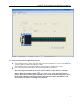
ReDAQ® Shape Software for MAQ®20 User Manual 5.2 Toolbox Usage The Toolbox contains 18 different Tools, many of which have several different styles. To open or close the toolbox window, click on the toolbox icon or select Toolbox from the View pull down menu. To select different tools use the tools scroll bar at the top of the window. To select a Tool, click on the image of the Tool and it will be highlighted.
ReDAQ® Shape Software for MAQ®20 User Manual 5.
ReDAQ® Shape Software for MAQ®20 User Manual All of the Tools can easily be selected from the Toolbox and inserted into a project. From there they can be moved, resized, cut, copied, pasted or deleted using simple point and click operations. Double clicking on a given Tool will open the properties window for the Tool where detailed settings can be changed.
ReDAQ® Shape Software for MAQ®20 User Manual 5.3.1 Chart Recorder Tool ® The Chart Recorder Tool displays data from analog input channels in the MAQ 20 data acquisition system. Data can be displayed from multiple channels in multiple modules simultaneously. To change the Chart Recorder Tool properties, double click on the device to open the Properties window. Only the Appearance, Behavior, Graph and Layout categories contain parameters that are useful to ® modify when interfacing to the MAQ 20.
ReDAQ® Shape Software for MAQ®20 User Manual 5.3.2 Scope Tool ® The Scope Tool displays data from analog input channels in the MAQ 20 data acquisition system. Data can be displayed from multiple channels in multiple modules simultaneously To change the Scope Tool properties, double click on the device to open the Properties window. Only the Appearance, Behavior, Graph and Layout categories contain parameters that are useful to modify when ® interfacing to the MAQ 20.
ReDAQ® Shape Software for MAQ®20 User Manual 5.3.3 XY Plot Tool ® The XY Plot Tool can display data from analog input channels in the MAQ 20 data acquisition system. Any channel can be chosen for the X-axis and Y-axis. The number of samples to display can be specified. Once the number of samples to display has been exceeded, the display will refresh and the prior data will be erased. To change the XY Plot Tool properties, double click on the device to open the Properties window.
ReDAQ® Shape Software for MAQ®20 User Manual 5.3.4 Discrete Waveform Graph Tool ® The Discrete Waveform Graph Tool displays the data for discrete input channels in the MAQ 20 data acquisition system. The X-axis represents the number of samples collected from the system and is shown at the top of the display and the Y axis shows the logic states 0 or 1 for the channels. Data can be displayed or hidden using the +/- box at the top left corner of the plot.
ReDAQ® Shape Software for MAQ®20 User Manual 5.3.5 Knob Tool ® The Knob Tool outputs data to analog output channels in the MAQ 20 data acquisition system. To change the Knob Tool properties, double click on the device to open the Properties window. Only the Appearance, Behavior, Layout and Scale categories contain parameters that are useful to modify when ® interfacing to the MAQ 20. Assign the analog output channel to send data to with the Knob Tool by using the Knob Output pull down selection box.
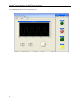
ReDAQ® Shape Software for MAQ®20 User Manual 5.3.6 Meter Tool ® The Meter Tool displays data from analog input channels in the MAQ 20 data acquisition system. To change the Meter Tool properties, double click on the device to open the Properties window. Only the Appearance, Behavior, Layout and Scale categories contain parameters that are useful to modify when ® interfacing to the MAQ 20. Assign the analog input channel to display in the Meter Tool by using the Meter Input pull down selection box.
ReDAQ® Shape Software for MAQ®20 User Manual 5.3.7 Gauge Tool ® The Gauge Tool displays data from analog input channels in the MAQ 20 data acquisition system. To change the Gauge Tool properties, double click on the device to open the Properties window. Only the Appearance, Behavior, Layout and Scale categories contain parameters that are useful to modify ® when interfacing to the MAQ 20. Assign the analog input channel to display in the Gauge Tool by using the Gauge Input pull down selection box.
ReDAQ® Shape Software for MAQ®20 User Manual 5.3.8 Tank Tool ® The Tank Tool displays data from analog input channels in the MAQ 20 data acquisition system. To change the Tank Tool properties, double click on the device to open the Properties window. Only the Appearance, Behavior, Layout and Scale categories contain parameters that are useful to modify when ® interfacing to the MAQ 20. Assign the analog input channel to display in the Tank Tool by using the Tank Input pull down selection box.
ReDAQ® Shape Software for MAQ®20 User Manual 5.3.9 Slide Tool ® The Slide Tool performs both input and output functions for analog I/O channels in the MAQ 20 data acquisition system. If an analog input channel is assigned to the Tool, the slide position represents the analog input channel reading. If an analog output channel is assigned to the Tool, moving the slide will generate a scaled output to the assigned analog output channel.
ReDAQ® Shape Software for MAQ®20 User Manual 5.3.10 Thermometer Tool ® The Thermometer Tool displays data from analog input channels in the MAQ 20 data acquisition system. To change the Thermometer Tool properties, double click on the device to open the Properties window. Only the Appearance, Behavior, Layout and Scale categories contain parameters that are useful to ® modify when interfacing to the MAQ 20.
ReDAQ® Shape Software for MAQ®20 User Manual 5.3.11 Numeric Edit Tool The Numeric Edit Tool performs both input and output functions for analog I/O channels and for discrete ® I/O channel special functions in the MAQ 20 data acquisition system. If an analog input channel is assigned to the Tool, it will display the analog input channel reading. If an analog output channel is assigned to the Tool data entered in the numeric edit box will be output to the assigned analog output channel.
ReDAQ® Shape Software for MAQ®20 User Manual 5.3.12 Switch Tool The Switch Tool is a multiple output device that can have up to four outputs which can each be set up with the following functions: Set discrete output, channels, to 1 = On or 0 =Off. Set analog output channels to a preset, non-zero value of 1 = On or 0 = Off. The Switch Tool can be configured to one of three Switch Types: On / Off, On Only, or Off Only.
ReDAQ® Shape Software for MAQ®20 User Manual 5.3.13 LED Tool The LED indicator Tool can be used to monitor discrete input channels or analog input channels. A discrete input channel value of 1 turns the LED on and a value of 0 turns the LED off. An analog input channel value greater than a user selected preset value turns the LED on and a value less than the preset value turns the LED off. Multiple LED’s can be connected to the same digital or analog input channel.
ReDAQ® Shape Software for MAQ®20 User Manual 5.3.14 Label Tool The Label Tool allows creation of short text labels which can be placed anywhere on the Present panel to document, notate or clarify a project. To use a Label, select it from the Toolbox and place it on the Present panel. Default text for the Label is ‘Label’. To modify this, double click the box to open the Properties box, then, under the Appearance heading and Text item, enter the desired text.
ReDAQ® Shape Software for MAQ®20 User Manual 5.3.15 Button Tool and High Level Timer Functions The Button Tool is a multiple output device that can have up to four outputs which can each be set up with the following functions: Set discrete output channels to 1 = On or 0 = Off. Set analog output channels to a preset, non-zero value = On or to 0 = Off. Reset alarm latched mode. Timer1 and/or Timer2 arm/disarm. Timer start/stop for countdown timer, 24 hour timer and date/time timer.
ReDAQ® Shape Software for MAQ®20 User Manual Count down timer operation: When the Switch is turned on, the first event is executed and then the first countdown sequence starts. When the count is zero, execution continues with the next configured event and timer and this sequence will continue until all configured events are finished. Example 1: A Count Down timer output starts at Event On, counts down to 1:10:30 then turns Off.
ReDAQ® Shape Software for MAQ®20 User Manual 24-hour day timer operation: When the switch is turned on, the first event is executed, then the first 24-hour timer starts. When the system time matches the programmed time, execution continues with the next configured event and timer and this sequence will continue until all configured events are finished. Example 1: A 24 Hour Day timer output starts at Event Off at 8:30:00 AM. At 9:00:00 AM it turns On.
ReDAQ® Shape Software for MAQ®20 User Manual 5.3.16 Group Box Tool The Group Box Tool is used to draw a box around a group of Tools on the Present panel. It does not affect interaction between Tools or project execution. To use a Group Box, select it from the Toolbox and place it on the Present panel. Once placed, the box can be resized to encompass any of the Tools placed in a project. If desired, Group Box properties can be modified by double clicking the box and opening the Properties box.
ReDAQ® Shape Software for MAQ®20 User Manual 5.3.17 Picture Box Tool The Picture Box Tool can be used to display any type of image file on the Present panel, including photographs of objects or graphs and plots. All common formats are supported. To open an image file, select the Picture Box Tool from the Toolbox and place it on the Present panel. Next, double click the item to open the Properties box. Image selection is made under the Appearance heading and Image item.
ReDAQ® Shape Software for MAQ®20 User Manual 5.3.18 Text Box Tool The Text Box Tool places a box on the Present panel where notes or instructions can be written. To use a Text Box, select it from the Toolbox and place it on the Present panel. Once placed, text can be added by placing the cursor in the Text Box and typing. If desired, Text Box properties can be modified by double clicking the box and opening the Properties box.
ReDAQ® Shape Software for MAQ®20 User Manual 6.0 Quick Start Examples 6.1 Closed Loop Control This closed loop control example demonstrates the implementation of a “bang-bang” temperature o o controller. It sets the temperature of a material to 75 C with a dead band of 2 C. The controller uses a discrete output channel to turn on a heater when the process first starts. When the temperature of the o o material reaches 75 C, the heater will turn off.
ReDAQ® Shape Software for MAQ®20 User Manual Step 4: Using the Present panel: Select a Thermometer Tool from the Toolbox to monitor the material temperature and place it on o the panel. Open the Properties window of the Tool and set the range of the Tool to 0-100 C using the Scale category of the Properties window and assign analog input channel 1_JTC_1_0 to the Tool using the Thermometer Input pull down selection box.
ReDAQ® Shape Software for MAQ®20 User Manual 6.2 Demonstration Projects ® The ReDAQ Shape Software for MAQ 20 download comes with 9 demonstration projects which show how to use the many available Tools. These projects are located in the ReDAQ Shape Software for ® MAQ 20 base file folders for both the Developer and User versions which have default locations and names of …\Dataforth\MAQ20\ReDAQ Shape MAQ20 Vx.xx Developer and …\Dataforth\MAQ20\ReDAQ Shape MAQ20 Vx.xx User respectively.
ReDAQ® Shape Software for MAQ®20 User Manual 6.2.2 Demonstration Project #2: Gauge Tool Interface to Input Channel Filename Demo_Gauge.rsd or Demo_Gauge.rsu A Gauge Tool is assigned to analog input channel. The output of an analog channel has been scaled to 0 – 120 and the Gauge Tool has also been scaled to 0 – 120. Apply a voltage of 0-5V to the input of channel. The Gauge Tool will show the respective speed.
ReDAQ® Shape Software for MAQ®20 User Manual 6.2.3 Demonstration Project #3: NumericEdit Tool Interface to Input Channel Filename Demo_NumericEdit.rsd or Demo_NumericEdit.rsu A NumericEdit Tool is assigned to an analog input channel. Apply a voltage of 0-5V to the input of channel. The NumericEdit Tool will display the channel output.
ReDAQ® Shape Software for MAQ®20 User Manual 6.2.4 Demonstration Project #4: Scope Tool Driven by Output Channels Filename Demo_Scope.rsd or Demo_Scope.rsu A Scope Tool is configured for horizontal scale 0-100 samples and vertical scale 0-5V. Analog input channels 0 and 1 are assigned to the Tool. Connect a MAQ20-VO module Channel 0 output to a MAQ20-VDN module Channel 0 input and also connect the MAQ20-VO module Channel 1 output to the MAQ20-VDN module Channel 1 input.
ReDAQ® Shape Software for MAQ®20 User Manual 6.2.5 Demonstration Project #5: Tank Tool and Control Loop Feature Filename Demo_Tank.rsd or Demo_Tank.rsu This project uses closed loop control to fill a tank. Analog input channel 0 is connected to a low level limit sensor and analog input channel 1 is connected to a high level limit sensor. Analog input channel 0 is set for Control Loop, Tracking L, Low Limit 1.45V and Low Deadband 0. Analog input channel 1 is set for Control Loop, Tracking H, High Limit 3.
ReDAQ® Shape Software for MAQ®20 User Manual 6.2.6 Demonstration Project #6: Thermometer Tool File name Demo_Thermometer.rsd or Demo_Thermometer.rsu The Present panel has been configured to use a map of the Tucson, AZ area as the background image. Five Thermometer Tools have been placed in different suburban areas of the city. Each of the Tools has been assigned to a MAQ20-xTC input channel 0.
ReDAQ® Shape Software for MAQ®20 User Manual 6.2.7 Demonstration Project #7: Graph Tool And LED Tool For Discrete I/O Filename Demo_Timer.rsd or Demo_Timer.rsu This project shows the use of the Graph Tool and the high level ‘Timer’ Discrete I/O Special Function. The Discrete [DIOx] Settings have been configured to setup both Timer 0 and Timer 1 for PWM Generation. Timer 1 output is mapped to discrete output channels for PWM1. Timer 2 output is mapped to discrete output channels for PWM2.
ReDAQ® Shape Software for MAQ®20 User Manual 6.2.8 Demonstration Project #8: XY Plot Tool Interface to Output Channels Filename Demo_xyplot.rsd or Demo_xyplot.rsu The XY Plot Tool has been configured with analog input channel 0 as X-axis input and analog input channel 1 as Y-axis input and has been scaled accordingly. The display will reset every 90 samples. A Chart Recorder Tool has been configured to display analog input channels 0 and 1 and has been scaled accordingly.
ReDAQ® Shape Software for MAQ®20 User Manual 6.2.9 Demonstration Project #9: Process Simulator A Process Simulator has been developed to demonstrate the power features of the ® ® MAQ 20 data acquisition system and the ease of use of the ReDAQ Shape Software for ® the MAQ 20. Filename Process Simulator.rsd or Process Simulator.rsu ® Contact the factory to obtain a demonstration system comprised of a MAQ 20 data acquisition system connected to the Process Simulator.
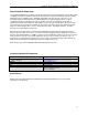
ReDAQ® Shape Software for MAQ®20 User Manual DATAFORTH WARRANTY Applying to Products Sold by Dataforth Corporation a. General. Dataforth Corporation (“Dataforth”) warrants that its products furnished under this Agreement will, at the time of delivery, be free from defects in material and workmanship and will conform to Dataforth's applicable specifications or, if appropriate, to buyer's specifications accepted in writing by Dataforth.
(4) DATAFORTH’S LIABILITY ARISING OUT OF THE PRODUCTION, SALE OR SUPPLY OF PRODUCTS OR THEIR USE OR DISPOSITION, WHETHER BASED UPON WARRANTY, CONTRACT, TORT OR OTHERWISE, SHALL NOT EXCEED THE GREATER OF EITHER US$1000.00 (ONE THOUSAND DOLLARS U.S.A. CURRENCY) OR THE ACTUAL PURCHASE PRICE PAID BY BUYER FOR DATAFORTH'S PRODUCTS. DATAFORTH'S LIABILITY FOR ANY CLAIM OF ANY KIND SHALL IN NO CASE EXCEED THE OBLIGATION OR LIABILITY SPECIFIED IN THIS WARRANTY. d. Technical Assistance.
Application Support Dataforth provides timely, high-quality product support. Call 1-800-444-7644 TOLL-FREE. Returns/Repair Policy All warranty and repair requests should be directed to the Dataforth Customer Service Department at (520) 741-1404. If a product return is required, request a Return Material Authorization (RMA) number. You should be ready to provide the following information: 1. 2. 3. 4. 5. Complete product model number. Product serial number.