
Owner's manual


Full IP65 Chassis LCD
IP65 Cable/Pin Define
Cable List
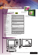
IO Layout
3 pin DC Power
Back Side (I/O)
10 pin VGA
connector
(IP65)
Optional
touch/others
LCD IP65 connector PC side IO type
DC power 3pin Female(2.5 fai)
USB(optional) 10pin Male(type A)
RS232(optional) 10pin Female(D-sub 9)
VGA 10pin Male(D-sub 15)
DC Power
RS232
USB
VGA
3
2
1
Pin No. Symbols Colo r Pin No. Symbols Colo r
CN1-1
CN1-3
CN1-2
CN2
CN1
VCC
GND
Shie ld
VCC
GND
Shie ld
Red
Bla ck
Red
Bla ck
Pin No. Sym bols Co lor Pin No. Sym bols Co lor
CN1-1
CN1-2
CN1-3
CN1-4
CN1-5
CN1-6
CN1-7
CN1-8
CN1-9
CN1-10
CN2-1
CN1-6
CN1-2
CN1-7
CN1-3
CN1-8
CN1-4
CN1-9
CN1-5
CN1-10
DCD-CON2
DSR-CON2
RXD-CON2
RTS-CON2
TXD-CON2
CTS -CON2
DTR -CON2
RI-CON2
GND-CON2
NC
DCD-CON2
DSR-CON2
RXD-CON2
RTS-CON2
TXD-CON2
CTS -CON2
DTR -CON2
RI-CON2
GND-CON2
NC
Green
Brow n
Red
Orang e
Blue
Whi te
Purpl e
Yellow
Black
Green
Brow n
Red
Orang e
Blue
Whi te
Purpl e
Yellow
Black
Pin No. Symbols Color Pin No. Symbols Color
CN1-1
CN1-2
CN1-3
CN1-4
CN1-5
CN2-1
CN2-2
CN2-3
CN2-4
VCC
D-
D+
GND
Shield
VCC
D-
D+
GND
Red
White
Gren
Black
Red
White
Gren
Black
1.0
First release
Mar-19-09
Rev. Reasons Revised Date
1.1
Spec change
Oct-12-10