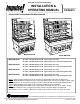
READ AND SAVE THESE INSTRUCTIONS INSTALLATION & OPERATING MANUAL PN 99574 OPEN REFRIGERATED SERVICE DROP-IN REFRIGERATED SELF-SERVICE MERCHANDISER MERCHANDISER Model DO3637R Model DO4837R Model DO3637R 38 1/8”L x 28 5/8”D x 37 1/4”H (Upper Display Case Only) 38 1/8”L x 28 5/8”D x 61 1/8”H (Upper Display Case + Drop-In Refrigeration Unit) Model DO4837R 50 1/8”L x 28 5/8”D x 37 1/4”H (Upper Display Case Only) 50 1/8”L x 28 5/8”D x 61 1/8”H (Upper Display Case + Drop-In Refrigeration Unit) Model DO36
TABLE OF CONTENTS OVERVIEW AND WARNINGS ...………………………..…………………..…….………….....….. 3 CUSTOMER CABINET PROVISIONS…………………..…………………..…….………….....….. 4 CLEARANCE AND AIR FLOW ...………………………..…………………..…….………….....….. 5 VENTING INSTRUCTIONS FOR AIR INTAKE / EXHAUST - DO3637R …………………….. 6 VENTING INSTRUCTIONS FOR AIR INTAKE / EXHAUST - DO4837R …………………….. 7 VENTING INSTRUCTIONS FOR AIR INTAKE / EXHAUST - DO3623R …………………….. 8 INSTALLATION ……………………………………………………………………………………….. 9 START-UP AND OPERATION ..
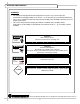
OVERVIEW AND WARNINGS OVERVIEW • • • The Structural Concepts® Oasis® refrigerated self-service cases are designed to merchandise packaged products at 5° Celsius / 41° Fahrenheit or less product temperatures. These cases should be installed and operated according to the following instructions to insure proper performance. This unit is designed for the display of products in ambient store conditions where temperatures and humidity are maintained at a maximum of 24°C / 75°F and 55% relative humidity.
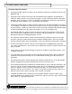
CUSTOMER CABINET PROVISIONS Customer Cabinet Provisions • Customer provided cabinet must adhere to the minimum requirements in ANSI/UL Std. 471 and ANSI/NSF Std. 7.
CLEARANCE AND AIR FLOW Service Top Cutout Dimensions Note: See Manual Cover for DO3637R, DO4837R, DO3623R & 4823R Service Top Cutout Dimensions. Clearance Dimensions The Refrigerated section must maintain airflow clearance. Dimensions are as follow. 1. 4" Minimum Spacing from bottom of refrigeration frame to bottom of cabinet or floor required for adequate air flow. 2. 9 1/2" Countertop / Facia enclosure space on cabinets or counter to allow for pullout system slide-out. 3.
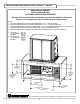
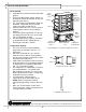
VENTING INSTRUCTIONS FOR AIR INTAKE / EXHAUST - DO3637R BACK VIEW OF CABINET AFTER POSITIONED ON CUSTOMER-SUPPLIED COUNTER/BASE Warning: The minimum intake and exhaust areas must be allowed (as illustrated below) or case temperatures may fluctuate beyond safe parameters. NOTES: 1. BACK OF CABINET MUST BE VENTED A MINIMUM OF 13” x 13” FOR AIR INTAKE. 2. BACK OF CABINET MUST BE VENTED A MINIMUM OF 10 1/2” x 19” FOR AIR EXHAUST. 3. BACK OF CABINET MUST PROVIDE A MINIMUM OF 15” x 32” FOR MAINTENANCE ACCESS.
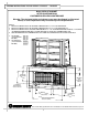
VENTING INSTRUCTIONS FOR AIR INTAKE / EXHAUST - DO4837R BACK VIEW OF CABINET AFTER POSITIONED ON CUSTOMER-SUPPLIED COUNTER/BASE Warning: The minimum intake and exhaust areas must be allowed (as illustrated below) or case temperatures may fluctuate beyond safe parameters. NOTES: 1. BACK OF CABINET MUST BE VENTED A MINIMUM OF 13” x 25” FOR AIR INTAKE. 2. BACK OF CABINET MUST BE VENTED A MINIMUM OF 19” x 21” FOR AIR EXHAUST. 3. BACK OF CABINET MUST PROVIDE A MINIMUM OF 15” x 45” FOR MAINTENANCE ACCESS.
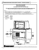
VENTING INSTRUCTIONS FOR AIR INTAKE / EXHAUST - DO3623R & DO4823R BACK VIEW OF CABINET AFTER POSITIONED ON CUSTOMER-SUPPLIED COUNTER/BASE Warning: The minimum intake and exhaust areas must be allowed (as illustrated below) or case temperatures may fluctuate beyond safe parameters. NOTES: 1. BACK OF CABINET MUST BE VENTED A MINIMUM OF 10 1/2” x 11” FOR AIR INTAKE. 2. BACK OF CABINET MUST BE VENTED A MINIMUM OF 3/4” x 15” FOR AIR EXHAUST. 3.
INSTALLATION 1. Remove Case From Skid Caution: Case must always remain supported or center of gravity may allow case to fall. Slide to rear of skid and tip backward off skid while maintaining support. See illustration below. 2. Display Case Setup • SCC® Service Drop-In Refrigerated Merchandiser Case consists of two sections: The Upper Display Case and Drop-In Refrigerated Section. • As both sections make up one conjoined unit, it is both large and heavy.
START-UP AND OPERATION Case Start-Up • • • • • • Plug cord into a certified electrical outlet with ground. Turn on the Main Power Switch. Switch is in the Drop-In Refrigerated Section on the rear right hand side of base. The Temperature Control Module (LED) will illuminate. Evaporator coil fans and the compressor motor should turn on. From the front of the case, raise the deck to confirm that the coil fans are functioning properly. Turn on the lights.
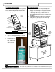
MAINTENANCE FUNDAMENTALS Adjustable Shelf • • • Adjustment of the angle of the shelves can be made by pivoting the lower portion of the shelf bracket in the upright. The shelves can be adjusted to an angle of: 0, 5, and 10 degrees. See illustration at right. Shelf Assembly Shelf Bracket Shelf Assembly Removal • • • • Shelves can be removed for cleaning or adjustments For lighted shelving, turn off power, unplug the light cord. Lift shelf straight up to separate from brackets. Remove brackets.
MAINTENANCE FUNDAMENTALS, CONTINUED Warning, disconnect power before providing maintenance and service to unit. Assembly or disassembly and servicing to be accomplished by licensed electrical contractor. Evaporator Coil Fans Access and Removal • Fan Shroud Fans may be accessed by removing Deck (covering Fan Shroud, Fan Housing and Coil). See illustrations at right. Coil Fan Housing Light Ballast Access Light ballast is located inside the Electrical JBox.
MAINTENANCE FUNDAMENTALS, CONTINUED Removing the Rear Doors • • • • • Remove Thumbscrews (4 each side). Thumbscrew removal will allow Rear Doors to be removed. See illustration on this page for locations of Thumbscrews, Nuts, Perforated Acrylic Plenum, etc. Move the doors toward the center of the case. Starting with the Outer Door (right hand door from rear of the case), individually lift each door up toward top of the case and pivot the bottom of door out.
REFRIGERATION FUNDAMENTALS Refrigeration Access, Connections & Servicing Assembly or disassembly and servicing to be accomplished by licensed refrigeration contractor. • • • • • Refrigeration Unit slides directly out from lower section to allow for servicing. Service connections are located in the Refrigeration Slide-Out (shown at right). Refrigeration Unit is equipped with evaporator pan for case condensation.
REFRIGERATION SLIDE-OUT EXPLODED PICTORIAL The following images show the various parts pertaining to the Refrigeration Unit (that is slid directly out from lower section) to be serviced. Condensing Coil (and internal fan) Electrical Junction Box Refrigeration Service Valve Capacitor Sight Glass Condensate Pan Receiver Copper Tubing Flexible Hose Connections Condensing Unit Dryer Filter Copper Tubing R 888 Porter Rd. Muskegon, MI 49441 Phone: 231.798.8888 Fax: 231.798.4960 www.
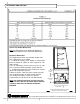
TECHNICAL INFORMATION SHEET - MODEL DO3637R R 888 Porter Rd. Muskegon, MI 49441 Phone: 231.798.8888 Fax: 231.798.4960 www.structuralconcepts.
TECHNICAL INFORMATION SHEET - MODEL DO4837R R 888 Porter Rd. Muskegon, MI 49441 Phone: 231.798.8888 Fax: 231.798.4960 www.structuralconcepts.
TECHNICAL INFORMATION SHEET - MODEL DO3623R R 888 Porter Rd. Muskegon, MI 49441 Phone: 231.798.8888 Fax: 231.798.4960 www.structuralconcepts.
TECHNICAL INFORMATION SHEET - MODEL DO4823R R 888 Porter Rd. Muskegon, MI 49441 Phone: 231.798.8888 Fax: 231.798.4960 www.structuralconcepts.
TROUBLESHOOTING Product is Drying Out Check the relative humidity in the store. Water on the Floor Check that all of the hoses are connected. Check that the drain trap is free of debris. Check that the case is aligned properly. Excessive Fan Noise Check that nothing is obstructing the blade rotation. Check that the fan shroud is properly secured. Confirm the utility power is on. System is not Operating Check that the MAIN power switch is on. Check that the unit is properly plugged in.
TROUBLESHOOTING, CONTINUED Alarm Going Off, CPC ESC3 E0 flashing, Air probe has failed. E1 flashing, Defrost termination or product probe has failed. L0 flashing, Low temperature alarm. H1 flashing, High temperature alarm. Ed flashing, Defrost timeout has occurred (did not terminate correctly). dF flashing, Controller is in defrost mode (not and alarm). Compressor is running is a normal condition. If a large amount of warm product was added to the case, it will take time for the temperature to adjust.
CLEANING SCHEDULE Cleaning Daily Weekly Monthly Clean Case Exterior X Clean outside surface of front curved glass with a household or commercial glass cleaner. X Clean wood, laminate and painted surfaces with a mild soap and water solution and a soft cloth . X Clean Case Interior Task Remove rear panel. Clean under case with vacuum. Shelves may be cleaned with a household or commercial glass cleaner. X X Remove the decks and clean with soap and water.
CPC® CONTROLLER - OVERVIEW Controller Overview The CPC® ESC3 series is an electronic refrigeration controller that provides control of compressor, fan and defrost management. The ESC3 provides control of a compressor (or solenoid) valve in response to temperature variations. Temperature Control Temperature control in the ESC3 is accomplished by comparing the temperature reading of the case temperature probe against the temperature set point. The compressor output is used to control the temperature.
CPC® - ESC3 CONTROLLER OPERATION Interface - The ESC3 features a 3 digit LED display that shows the case temperature. Alternately, the display can be configured to display the product temperature if a product temperature probe is connected. The temperature can be displayed in either 0C or 0F. -15 Alarm Key - The Alarm key illuminates when the controller has detected an alarm condition. This key is also used to reset an alarm condition and to enter the setup mode (allowing set points to be changed).
CPC® ESC3 SET POINT CHANGING INSTRUCTIONS Viewing and Changing the Temperature Set Point The temperature set point is the comparison point for the control temperature input. To change the set point value: 1. Press the Alarm key for 3 seconds, until the set point is displayed and blinking. 2. Press the compressor key or defrost key to raise/lower the value. 3. Press the Alarm key again to accept the new value. Changing Other Set Points There are two levels of set points in the ESC3.
WARRANTY All sales by Structural Concepts Corporation (SCC) are subject to the following limited warranty. “Goods” refers to the product or products being sold by SCC. Warranty; Remedies; Limitations.
TECHNICAL SERVICE TECHNICAL SERVICE DEPARTMENT 1.800.433.9489 R 888 Porter Rd. Muskegon, MI 49441 Phone: 231.798.8888 Fax: 231.798.4960 www.structuralconcepts.