
Installation Manual


in-lite INSTALLATION MANUAL SMART BRIDGE
www.in-lite.com 01-12-2021
Safety
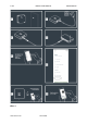
Along with the SMART BRIDGE a power adapter is supplied. This is the only way
to connect the product to the main power source of 100-230V. When the adapter
is connected in a wrong or insufficient way the SMART BRIDGE will show with a
led signal that it’s facing a power supply issue. Intill this issue is solved it will do
so.
Description Power limitation Smartbridge
The adapter limits the power supply to 12V DC with a max. of 1A. The current of
the incoming supply line is further limited by a 1.1A resettable fuse.
The supplies for the processing are derived in the following way:
1. 12V -> 5V switchmode converter (buck)
2. 5V -> 3V3 switchmode converter (buck)
3. 5V -> 1V5 switchmode converter (buck) for DDR memories
4. 3V3 -> 2V5 linear converter (LDO) for Ethernet interface.
The power for the main processor (A20) is derived from the 3V3 supply by IC15
(AXP209):
1. 3V3 -> 1V2 switchmode converter (buck) for CPU
2. 3V3 -> 1V2 switchmode converter (buck) for internal CPU
3. 3v3 -> 3V0 linear converter (ldo) for VDD_RTC