
Operators Manual Owner manual


Table Of Contents
- 1 Introduction
- 2 Safety
- 3 General Specifications
- 4 Sensor Specifications
- 5 Instrument Overview
- 6 System Components
- 7 Probe Setup
- 8 Communication Settings and Calibration
- Connect the Instrument to the Computer
- Connect the Instrument to Win-Situ 5 Software
- First Screen (Data Tab)
- Set Communication Outputs
- Modbus Setup
- SDI-12 Setup
- View and Record Data
- Calibrate and Set Up Sensors
- Set Parameter Units and Sentinel Values
- RDO Sensor Calibration
- Conductivity Calibration
- Pressure/Level
- pH/ORP Calibration
- 9 Controller Requirements and Connections
- 10 Care and Maintenance
- 11 Declaration of Conformity
800-446-1500 17 www.in-situ.com
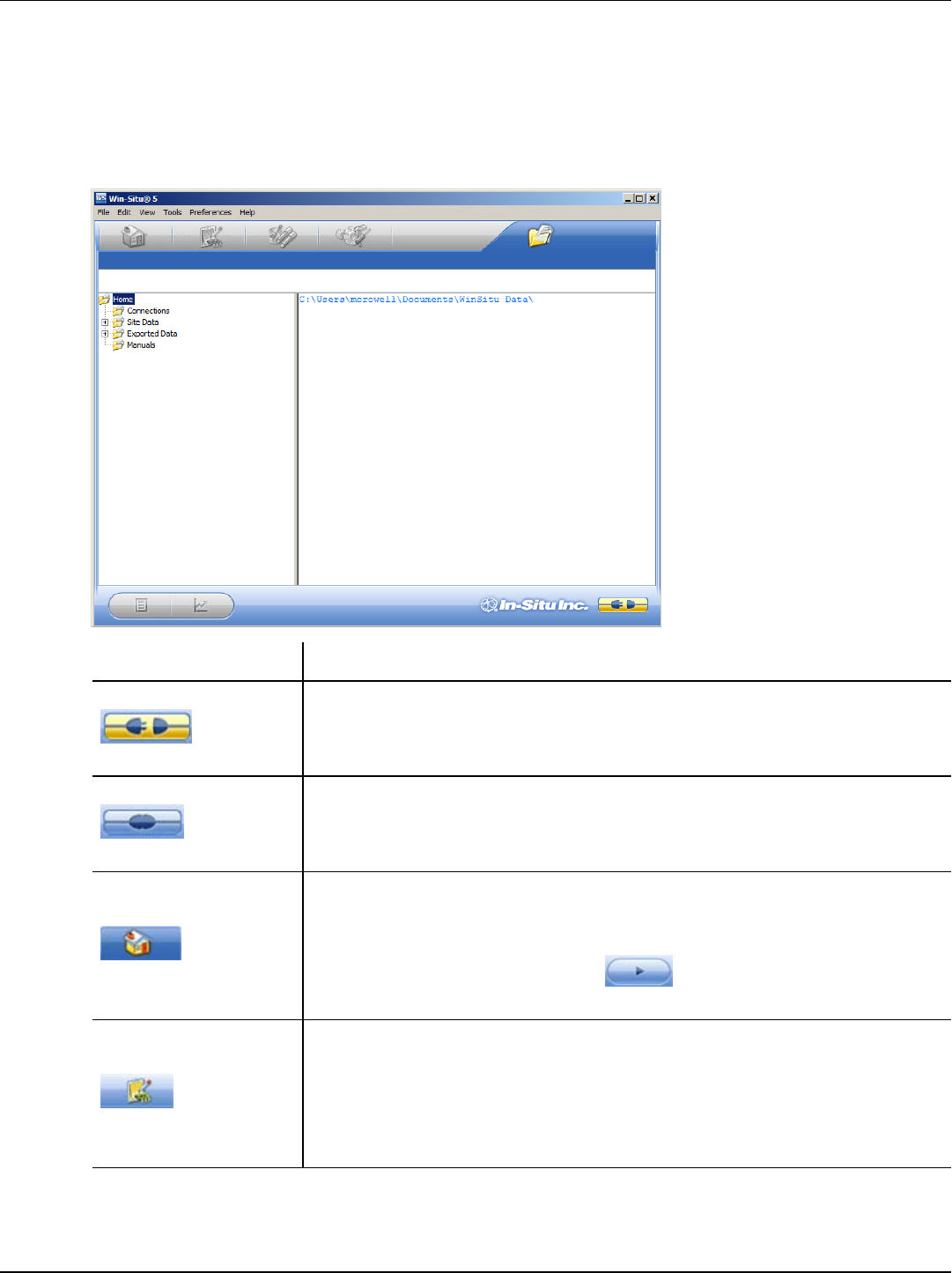
First Screen (Data Tab)
When you open Win-Situ 5 Software, the Data tab appears. The left side of the screen
contains a file tree where you can view data you have exported to Microsoft Office
Excel. The disconnected plug icon in the lower-right corner of the screen indicates that
the software is not yet communicating with an instrument.
Screen Element Definition
The disconnected plug indicates the instrument is not
communicating with the software. Click to establish communication
with a connected instrument.
The connected plug indicates the instrument is communicating
with the software. Click to disconnect the software from the
instrument.
The Home tab displays real-time readings from the instrument.
When connection to the instrument is first established, the software
displays one reading of all available parameters in light gray.
You must click the Play button at the bottom of the screen
to view real-time readings.
The Logging tab displays a list of logs stored in the connected
instrument. When you click the Logging tab, it can take a moment
for the software to retrieve information from the instrument. The
Logging tab is not applicable for non-logging instruments such as
the RDO PRO-X Probe and the Aqua TROLL 400.