
Operators Manual Owner manual


Table Of Contents
- 1 Introduction
- 2 Safety
- 3 General Specifications
- 4 Sensor Specifications
- 5 Instrument Overview
- 6 System Components
- 7 Probe Setup
- 8 Communication Settings and Calibration
- Connect the Instrument to the Computer
- Connect the Instrument to Win-Situ 5 Software
- First Screen (Data Tab)
- Set Communication Outputs
- Modbus Setup
- SDI-12 Setup
- View and Record Data
- Calibrate and Set Up Sensors
- Set Parameter Units and Sentinel Values
- RDO Sensor Calibration
- Conductivity Calibration
- Pressure/Level
- pH/ORP Calibration
- 9 Controller Requirements and Connections
- 10 Care and Maintenance
- 11 Declaration of Conformity
800-446-1500 36 www.in-situ.com
RS485 Network Guidelines
The instrument uses RS485 as its main digital communications link. RS485 is often
used in an industrial setting as a small device network. There are some installation
guidelines to follow when configuring an RS485 network with this instrument. See the
Modbus and SDI-12 Reference Guide.
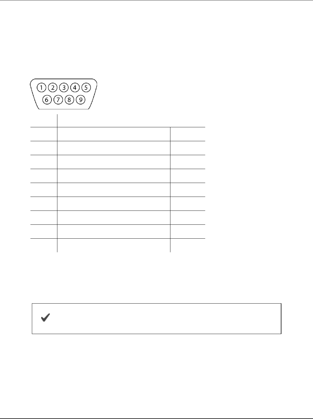
DB-9 Diagram
Pin Signal Name
1 Carrier Detector DCD
2 Receive Data RXD
3 Transmit Data TXD
4 Data Terminal Ready DTR
5 Signal Ground/Common GND
6 Data Set Ready DSR
7 Request to Send RTS
8 Clear to Send CTS
9 Ring Indicator RI
Communication Overview
The instrument can be programmed to use either Modbus or SDI-12. Modbus and SDI-
12 cannot be used at the same time. The protocol that is in use will block
communication of the other.
See the Aqua TROLL 400 Modbus and SDI-12 Reference Guide
for registers and programming information.
Prior to connecting the instrument to the controller, you must configure communication
settings using the Comm Kit Software and the Communication Device.