
Owner manual


14 Buoy Transceiver
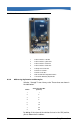
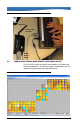
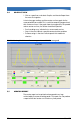
FIGURE 8. Transceiver interior
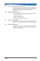
4.2.2 Addressing Explanation and Examples
Switches 1 through 7 have a binary value. These values are shown in
the table below:
By adding all the values of the switches that are in the “ON” position,
you can determine the address.
1 Probe connection—red wire
2 Probe connection—green wire
3 Probe connection—blue wire
4 Probe connection—black wire
5 Probe ground—silver wire
6 Power 9–18 volts DC +
7 Power9–18 volts DC –
8 Radio module with integrated antenna
9 Transceiver addressing dip switches
Switch
Value (if in the “ON”
position)
11
22
34
48
516
632
764
8 128