Operator's Manual Con TROLL® PRO Information subject to change without notice. In-Situ, In-Situ logo, Baro Merge, BaroTROLL, HERMIT, iSitu, Pocket-Situ, RDO, RuggedCable, RuggedReader, TROLL, and Win-Situ are trademarks or registered trademarks of In-Situ Inc. © 2013. All rights reserved. 0085670 | Rev.
Copyright © 2009-2013 by In-Situ Inc. All rights reserved. This document contains proprietary information which is protected by copyright. No part of this document may be photocopied, reproduced, or translated to another language without the prior written consent of In-Situ Inc. Mailing and Shipping Address: In-Situ Inc. 221 East Lincoln Avenue Fort Collins, CO 80524 U.S.A. Phone: 970-498-1500 (international & domestic) Fax: 970-498-1598 Internet: www.in-situ.com Support: 800-446-7488 (U.S.A.
Table of Contents 1 Getting Started 6 Probe Installation Requirements Navigating Through the Menus Menu Diagram Initial Configuration Using the View Function Changing the Date and Time Display (Screen) Appearance Locking the Display Changing the Display Contrast Changing the Displayed Location Changing the Back-light Time Changing the Auto-Off Time (DC-L Model Only) Changing the Language On-Screen Icon Descriptions Setting the Log Interval Setting the Communications Preferences Setting the Device Address
Nominal Stability vs. Full Stability 19 19 Factory Recalibration 4 Aqua TROLL 100 and 200 Instruments Configuring Aqua TROLL 100 and 200 Options Conductivity/Alpha Coefficient Conductivity/Reference Temperature Conductivity/TDS Factor Level/Level Mode (Aqua TROLL 200 only) Level/Specific Gravity (Aqua TROLL 200 only) Calibration Interval Calibrating the Aqua TROLL 100 and 200 Instruments Calibrating Conductivity Zeroing the Pressure Sensor Setting a Level Reference Calibration Hints Nominal Stability vs.
Defaults 31 6 Level TROLL Instrument 32 Configuring Level TROLL Options Setting the Level Mode Entering the Specific Gravity Setting the Calibration Interval Calibrating the Level TROLL Instrument Zero Pressure Calibration Hints Nominal Stability vs.
Getting Started Probe Installation Requirements Before making any wiring connections between the probes and the module, make sure that the probes are set to their factory-default communication settings. If you are using brand new probes, you do not need to do anything. If you are using preconfigured probes, use Win-Situ 5 Software to reset the default communication settings. 1. Open Win-Situ Software and connect to the probe. 2.
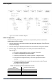
Menu Diagram Figure 1.2 ConTROLL PRO Menu Diagram Initial Configuration Enter the following information upon first use or anytime after you have restored the default settings on the controller. 1. Use the arrow keys to move up or down to the appropriate language. Select Enter to accept the language. 2. Use the arrow keys to adjust the Contrast level. Select Enter to accept the contrast. 3. Refer to Table 1 to determine your UTC value (Universal Coordinated Time, formerly GMT). a.
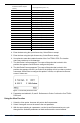
Region UTC Value (± numeric value) Australia Australian Capital Territory +10 (Daylight saving time +11) Australia South +9.5 (Daylight saving time +10.5) Australia Tasmania +10 (Daylight saving time +11) Australia Western +8 Canada Central -6 (Daylight saving time -5) Canada Eastern -5 (Daylight saving time -4) Canada Mountain -7 (Daylight saving time -6) Canada Yukon & Pacific -8 (Daylight saving time -7) Canada Atlantic -4 (Daylight saving time -3) Canada Newfoundland -3.
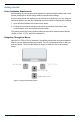
Figure 1.4 Probe A, probe B and probe C Probe A parameters are labeled with A. Probe B parameters are labeled with B, and Con TROLL PRO parameters are labeled with C. Changing the Date and Time 1. From the main screen, select Menu, Settings, Date & Time. 2. Three menu items will appear. l Date shown as: YYYY-MM-DD l Time shown as: HH:MM:SS l UTC shown as: ±HH:MM 3. Use Select to choose the menu item. 4. Use the arrow keys to choose the new setting. 5. Select Enter.
l l ON—The back-light stays on continuously. Interval—The back-light stays on for the specified interval after the last keyboard activity and then turns off. Press any key to turn the back-light on again. Changing the Auto-Off Time (DC-L Model Only) To conserve power, you can set the display to turn off after the keypad has not been used for a certain length of time. 1. From the main screen, select Menu, Settings, Display, Auto-off. 2. Select the desired option and press Enter.
On-Screen Icon Descriptions Table 2. Icons and their descriptions Error with parameter or RDO PRO (RDO Classic Sensor Cap) has expired. Error with parameter Calibration nominally stable View Bluetooth wireless technology turned on Communication ongoing View locked View is not locked Level or Aqua TROLL: Factory calibration has expired. RDO PRO-X: RDO-X Sensor Cap has exceeded its recommended service period, or the cap has sustained significant abrasion and should be replaced.
IMPORTANT: Any change to the configuration of the parameters (add probe, delete probe, enable/disable parameters, change units, etc.) will cause the data log to be erased and restarted. Setting the Communications Preferences Setting the Device Address for the Controller (RS485 Instruments Only) 1. From the main screen, select Menu, Settings, Communication. 2. Select Address. 3. Enter a value between 1 and 245. The address of Probe A is the controller address plus 1.
3. When pairing between the controller and the Bluetooth device is successful the controller screen will show “Pairing Successful.” 4. Select OK. After a device is paired with the Con TROLL PRO, it can connect to the Con TROLL PRO any time Bluetooth is turned on. Administrator and Password Access You may set up the controller with passwords for an administrator and a single user. The User can access the Calibrate, Log Data, Hold Outputs, and Diagnostics menus.
Configuring Probes Adding a Probe After Initial Configuration or Deletion 1. From the main screen, select Menu, Settings, Probes. 2. Select Probe A or B, then Add Probe. 3. The Add Probe screen appears with the name of the sensor that is wired in this position. If there is no probe detected, the display will tell you that no probe is connected. Select Enter to add and configure the probe.
Setting Parameter Units 1. From the main screen, select Menu, Settings, Probes. 2. Select a probe. 3. Select parameters. 4. Use the arrow keys to scroll to the selected parameter. Select Enter. 5. Select Units. 6. Use the arrow keys to scroll to the correct unit of measure. Select Enter. Settings Parameter Resolution (Setting Significant Units) 1. From the main screen, select Menu, Settings, Probes. 2. Select a probe. (Remember that Probe C is the controller.) 3. Select Parameters. 4.
RDO PRO or RDO PRO-X Probe Configuring RDO PRO or RDO PRO-X Options The RDO PRO and the RDO PRO-X probes are both compatible with the Con TROLL PRO. Barometer 1. From the main screen, select Menu, Settings, Probes. 2. Select the RDO PRO or RDO PRO-X Probe. 3. Select Options, then Barometer. 4. Choose between Fixed or Automatic compensation. l l If you select “Fixed,” you must then enter a barometric value. If you select “Automatic,” the Con TROLL PRO will provide a barometric value to the probe.
l l Concentration—Choose this option if you want to calibrate the concentration values to a concentration obtained using another method. Defaults—Choose this option if you want to restore the default calibration values. 1-Point Calibration Water-Saturated Air 1. Remove the storage cap from the top of the calibration chamber and replace it with the vented calibration cap. 1 Storage cap 2 Vented calibration cap Figure 3.1 Storage cap and vented calibration cap shown together 2.
Figure 3.3 Beginning the 1-point calibration; accepting or canceling the calibration. Controller 2-Point Calibration (100% and 0% Saturation) 100% Calibration Point 1. Set up the calibration equipment. See page 17. 2. From the Con TROLL PRO Main screen, select Menu, Calibrate, RDO PRO or RDO PRO-X. 3. Select Saturation, then select 2-point cal. 4. Press OK to start the 100% saturation calibration. 5. You will see the Calibration Beginning icon next to the % Sat value.
6. You will see the Calibration Beginning icon next to the % Sat value. When the calibration is complete, choose Stable to accept the calibration or Cancel to return to the pre-existing calibration. Figure 3.5 Beginning the 2-point calibration; accepting or canceling the calibration 7. Once calibrated, remove the probe, and thoroughly rinse with water to remove any excess sodium sulfite. Calibration using the Concentration Option 1.
Aqua TROLL 100 and 200 Instruments Configuring Aqua TROLL 100 and 200 Options Conductivity/Alpha Coefficient 1. From the main screen, select Menu, Settings, Probes. 2. Select the Aqua TROLL 100 or 200 Instrument. 3. Select Options. 4. Select Conductivity, Alpha. 5. Use the arrow keys to enter the desired coefficient. 6. Select Enter. (The default value is 0.0191.) Conductivity/Reference Temperature 1. From the main screen, select Menu, Settings, Probes. 2. Select the Aqua TROLL 100 or 200 Instrument. 3.
Level/Specific Gravity (Aqua TROLL 200 only) 1. From the main screen, select Menu, Settings, Probes. 2. Select the Aqua TROLL 200 Instrument. 3. Select Options. 4. Select Level, Specific Gravity. 5. Choose Fixed or Automatic. l l For Fixed, enter a desired value and select Enter. For Automatic, the controller will configure the Aqua TROLL to calculate specific gravity automatically.
4. You will see the Calibration Beginning icon next to the μS/cm value. When the calibration reaches stability, choose Stable to accept the value or Cancel to return to the pre-existing calibration. Figure 4.1 Beginning the calibration; accepting or canceling the calibration Zeroing the Pressure Sensor Aqua TROLL 200 has been factory calibrated with NIST standards to a greater degree of accuracy than can be achieved in nearly any alternate setting.
Aqua TROLL 400 Instrument Configuring the Aqua TROLL 400 Sensor Options Barometer 1. From the main screen, select Menu, Settings, Probes. 2. Select the Aqua TROLL 400 Instrument. 3. Select Options. 4. Select RDO, Barometer. 5. Use the arrow keys to select “Fixed” or “Auto,” and press Enter. l l If you select “Fixed,” you must then enter a barometric value. If you select “Automatic,” the Con TROLL PRO will provide a barometric value to the probe.
1. From the main screen, select Menu, Settings, Probes. 2. Select the Aqua TROLL 400 Instrument. 3. Select Options. 4. Select Conductivity, Tref. 5. Use the arrow keys to enter the desired reference temperature. 6. Select Enter. (The default value is 25° C.) Conductivity/TDS Factor 1. From the main screen, select Menu, Settings, Probes. 2. Select the Aqua TROLL 400 Instrument. 3. Select Options. 4. Select Conductivity, TDS. 5. Use the arrow keys to enter the TDS factor. 6. Select Enter.
4. Select Pressure, Specific Gravity. 5. Select “Fixed” or “Auto.” If you select “Fixed,” use the arrow keys to enter a desired value, and select Enter. l If you select Auto, the Con TROLL PRO will configure the Aqua TROLL 400 to calculate specific gravity using the measurement from the conductivity sensor. l Calibration Interval This function will warn you when you are overdue for a user calibration by displaying the graph symbol on the screen. 1. From the main screen, select Menu, Settings, Probes.
l l Cal. Report—Choose this option to view the date of the last calibration. Press the More button to view the Slope and Offset values. Press the OK button when finished. Defaults—Choose this option if you want to restore the default calibration. 1-Point Calibration Water-Saturated Air 1. Place the sponge wafer in the bottom of the calibration chamber and saturate the sponge wafer with approximately 10 mL of water. 2.
7. You will see the “Calibration Beginning” icon next to the mg/L reading. When the calibration is complete, select Stable to accept the calibration or Cancel to return to the pre-existing calibration. Figure 5.3 Beginning the 1-point calibration; accepting or canceling the calibration 2-Point Calibration (100% and 0% Saturation) 100% Calibration Point 1. Set up the calibration equipment. See "1-Point Calibration" on page 26. 2.
4. You will see the Calibration Beginning icon next to the % Sat value. When the calibration is complete, choose Stable to accept the calibration or Cancel to return to the pre-existing calibration. Figure 5.5 Beginning the 2-point calibration; accepting or canceling the calibration 5. Once calibrated, remove the sensor, and thoroughly rinse to remove any excess sodium sulfite. Calibration using the Concentration Option 1.
7. If you select Stable, the Standard Value screen appears. The instrument autodetects the standard solution in which it was calibrated. Use the arrow keys if you need to change the calibration standard value, and select Enter. 8. Press the More key to view the cell constant. Figure 5.
9. When you select Stable, the Standard Value screen appears. The instrument autodetects the standard buffer in which it was calibrated. Use the arrow keys if you need to change the calibration buffer value, and select Enter. 10. If you are performing a multi-point calibration, you are prompted to place the probe in the next buffer, and press OK. 11. Continue in this manner until the calibration is complete. Calibrating the ORP Sensor 1. From the Con TROLL PRO main screen, select Menu, Calibrate. 2.
Cal. Report 1. From the main screen, select Menu, Calibrate. 2. Select the Aqua TROLL 400 Instrument. 3. Select the appropriate parameter. 4. Select Cal Report to view the last time the sensor was calibrated. Select More to view more calibration information. Defaults 1. From the main screen, select Menu, Calibrate. 2. Select the Aqua TROLL 400 Instrument. 3. Select the appropriate parameter. 4. Select Defaults and Enter to restore the sensor to factory calibrated values. 800-446-7488 31 www.in-situ.
Level TROLL Instrument Configuring Level TROLL Options Setting the Level Mode 1. From the main screen, select Menu, Settings, Probes. 2. Select the Level TROLL Instrument. 3. Select Options, then Level Mode. 4. Choose between Depth, Level-DTW, and Level-SE. l l l Depth is the depth of the water above the level sensor. Level-DTW (depth to water) is the distance from the top of a well casing or other level reference down to the water surface.
Calibration Hints Nominal Stability vs. Full Stability To meet the criteria for a valid calibration point, the change (delta) in sensor response is monitored over time. The controller is looking for the calibration solution temperature and the sensor readings to settle over a specific time period. The criteria for Full Stability are designed to meet the published specifications. The criteria for Nominal Stability are designed to shorten the calibration time when an approximate calibration is acceptable.
Current Loops and Relays Configure the Current Loops If you have wired 1 or 2 current loop outputs as described in the Con TROLL PRO Installation Manual, configure these outputs after all probes and parameters have been configured. 1. From the main screen, select Menu, Settings, Outputs, then Current Loops. 2. Choose the appropriate current loop. 3. Under each current loop, you will have 6 options to choose from. l Enable/Disable: Choose to enable or disable the current loop.
Alarms Setpoints and Deadbands High Alarm Mode l l The relay is turned on if the current reading is equal to or greater than the setpoint value. The relay is turned off if the current reading is less than or equal to the setpoint minus the deadband. Figure 8.1 High Alarm relay behavior Low Alarm Mode l l The relay is turned on if the current reading is equal to or less than the setpoint value. The relay is turned off if the current reading is greater than or equal to the setpoint plus the deadband.
Logged Data Con TROLL PRO Models AC-L and DC-L have logging capabilities. Parameters are logged according to a set value as described in Setting the Log Interval The logged parameters are those enabled in Enabling and Disabling Parameters Viewing Logged Data 1. From the main screen, select Menu, Data Log. 2. Select the probe and parameter that you want to view. Probe A parameters are labeled with A. Probe B parameters are labeled with B, and Con TROLL PRO parameters are labeled with C. 3.
3. Set the Con TROLL PRO in the Enable Pairing mode. From the main screen select Menu, Settings, Communication, Bluetooth, Enable pairing. 4. The Wizard will search for the Con TROLL PRO device. 5. Select the Con TROLL PRO device. 6. If you are prompted for a passkey or a PIN enter 0000. 800-446-7488 37 www.in-situ.
7. Click the Finish button. 8. Open the Bluetooth Devices utility. 9. Select the Options tab. Select the check boxes shown below. 800-446-7488 38 www.in-situ.
10. Click the COM Ports tab. Note the Port number of the Outgoing port (in this example, Port 17). You will need to select this port in the Win-Situ 5 Comm Settings window. Configuring the Bluetooth Utility for PCs Not Factory-Enabled with Bluetooth Communications (Example) The following example shows how to configure the Bluetooth utility provided with the Cirago Bluetooth USB Adapter using Toshiba 6.0 Software and Drivers.
3. Click the "New Connection" button to start the connection Wizard. Select the "Express Mode" option and click Next. Allow the unit to search for devices. 4. When the search is complete, the device list will be displayed. Each Con TROLL PRO will be displayed with their respective site names. If a site name is not yet programmed into the Con TROLL PRO, the displayed name will be the serial number of the unit. Select the Con TROLL PRO you want to connect to and click Next.
6. Each time you connect, you will have to enter the passkey. The passkey for the Con TROLL PRO is by default its serial number. In our example, we have to enter 123456. If an Administrator password is configured for the local display, the passkey will be that password. 7. Once connected, the connection manager will show the Bluetooth connection as active.
2. After wiring the stripped-and-tinned Rugged Cable, connect either a cable connect USB or RS232 TROLL Com communication cable to the twist-lock connector on the cable. 3. Attach the TROLL Com to a PC running Win-Situ 5 or a RuggedReader running Win-Situ Mobile. 4. Click the Connect button to initiate communications between the controller and the PC software. Connecting the Con TROLL PRO to Win-Situ 5 Software 1. Install Win-Situ 5 from the In-Situ software CD. Open Win-Situ 5. 2.
4. Click the Connect button. The Home screen appears. It displays the ambient temperature and barometric pressure measured by the Con TROLL PRO device. The software also creates a log file using the serial number of your Con TROLL PRO device. 5. Click the Logging tab. 6. Select the log and click the Download button. 800-446-7488 43 www.in-situ.
7. Click the My Data tab shown in the figure above. You can view your data in the right window or download it as a *.csv or *.txt file. 8. To export, right click the log in the data tree and select Export to CSV or Export to Text. 9. Click the Connect button to disconnect your Bluetooth communications. 800-446-7488 44 www.in-situ.
Downloading Data using Win-Situ Mobile and a RuggedReader Handheld PC Configuring the Bluetooth Utility on the RuggedReader PC 1. From the Start menu, select Settings. 2. Tap the Connections tab, then tap the Bluetooth icon. 3. Tap Add new device. Select the Con TROLL PRO device and tap Next. 4. Enter the passcode. The passcode for the Con TROLL PRO is by default its serial number. If an Administrator password is configured for the local display, the passkey will be that password.Tap Next.
5. Click Done, then select the Com Ports tab. Tap New Outgoing Port. 6. Select your Con TROLL PRO device. Tap Next. 7. Make note of the Com Port number (COM2 in this example). Tap Finish. 800-446-7488 46 www.in-situ.
Connecting the Con TROLL PRO to Win-Situ Mobile Software 1. Tap Start, then Win-Situ Mobile. 2. Tap File, then Comm Settings. 3. Select Customize serial settings and tap the forward arrow. A warning appears. Tap the Yes button. 800-446-7488 47 www.in-situ.
4. A series of screens will appear. Move through them by tapping the forward arrow button. l l Make sure that the Port Number matches the port number assigned by the Bluetooth Utility in the previous section. Make sure that ASCII, not RTU, is selected. Tap the Check Mark button. 5. You will return to the “Home” screen. Tap the yellow Connect button.The temperature and barometric pressure from the Con TROLL PRO will appear. 6. Tap the View menu, then select Logging. 800-446-7488 48 www.in-situ.
7. Tap the Con TROLL PRO log to highlight it. Then tap the Download button. Select the how much data to download: All, New, or a set Interval. Tap the Check Mark button to begin the download. 8. Tap the Check Mark button when the download is complete. You may also view the data now. Select Yes, to view the data. 9. The data log will open. Each parameter is selectable from the pull-down menu. 800-446-7488 49 www.in-situ.
10. To export the data to csv format, tap File, then Options. Tap Export All Now, then the Check Mark button to export all data from this log to csv. Bluetooth Special Hints The Bluetooth Connection Manager has several helpful functions. l l l 800-446-7488 Rename your Bluetooth connection to something more meaningful. Right click the connection in the Bluetooth connection manager and select the rename menu option. Use this menu to disconnect and connect the Bluetooth link.
Troubleshooting Diagnostics Con TROLL PRO diagnostics allow you to find serial numbers, firmware and hardware versions, calibration, and power information. 1. Select Menu, Diagnostics. 2. Select the probe, then Enter.
Finding Calibration Data and Constants 1. Select Menu, Diagnostics. 2. Select the probe, then Enter. 3. Scroll down to the Cal option. Select Enter. RDO PRO Stored calibration data Level TROLL Aqua TROLL Slope None Cell constant Offset None Cell constant 800-446-7488 52 www.in-situ.
Troubleshooting Power Issues Danger Only properly trained and qualified personnel should troubleshoot the power connections described here. See the Installation Manual for additional wiring and hazard information. Danger On AC models, make sure that power to the instrument is disconnected before removing the protective AC panel or troubleshooting AC connections. See the Installation Manual for additional wiring and hazard information. 800-446-7488 53 www.in-situ.
Troubleshooting Probe Connection Issues 800-446-7488 54 www.in-situ.
Troubleshooting Bluetooth Communications Issues 800-446-7488 55 www.in-situ.