
Instruction for Use


AUS
7
lt. 78
Voltage and
frequency
230-240V~ 50Hz (see data plate)
Power supply Max 2850-3105 W
Burners
may be adapted for use with any type
of gas shown on the data plate.
Directive 2002/40/EC on the label of
electric ovens.
Standard EN 50304-60350
Energy consumption for Natural
convection – heating mode:
Convection mode
Declared energy consumption for
Forced convection Class – heating
mode: Fan assisted.
APPLIANCE SPECIFICATIONS
Oven dimensions
HxLxP
Volume
This appliance conforms to the following
European Economic Community directives:
- 2006/95/EEC dated 12/12/06
(Low Voltage) and subsequent amendments
- 2004/108/EEC dated 15/12/04
Electromagnetic Compatibility)
and subsequent amendments
- 93/68/EEC dated 22/07/93 and
subsequent amendments.
- 2009/142/EEC dated 30/11/09 (Gas)
and subsequent amendments.
- 2012/19/EEC and subsequent
amendments.
.
Energy
Label
height 32,9 cm
width 59,5 cm
depth 39,4 cm
Gas connection
! Installation must be in accordance with this instruction manual, AS 5601.1
“gas installations” for installation and pipe sizing, local gas tting regulations,
municipal building codes, local electrical regulations and any other statutory
regulation by an authorised person.
Connection to the gas network or to the gas cylinder may be carried out using
a exible rubber or steel hose, in accordance with current national legislation
and after making sure that the appliance is suited to the type of gas with which
it will be supplied (see the rating sticker on the cover: if this is not the case see
below). When using liquid gas from a cylinder, install a pressure regulator which
complies with current national regulations.
! Make sure that the gas supply pressure is consistent with the values indicated
in the Table of burner and nozzle specications (see below). This will ensure
the safe operation and durability of your appliance while maintaining efcient
energy consumption.
! Flexible hose assembly (if used) must comply with AS/NZS 1869 Class B
or D, be of appropriate internal diameter, be kept as short as possible (not to
exceed 1.2 metres), must not be kinked or in contact with any hot surface.
The supply connection point shall be accessible with the appliance installed.
Gas connection using a exible rubber hose
Make sure that the hose complies with current national legislation. The
internal diameter of the hose must measure: 8 mm for a liquid gas supply;13
mm for a methane gas supply.
Once the connection has been performed, make sure that the hose:
• Does not come into contact with any parts which reach temperatures of
over 50°C.
• Is not subject to any pulling or twisting forces and that it is not kinked or
bent.
• Does not come into contact with blades, sharp corners or moving parts
and that it is not compressed.
• Is easy to inspect along its whole length so that its condition may be
checked.
• Is shorter than 1500 mm.
• Fits rmly into place at both ends, where it will be xed using clamps which
comply with current regulations.
! If one or more of these conditions is not fullled or if the cooker must be
installed according to the conditions listed for class 2 - subclass 1 appliances
(installed between two cupboards), the exible steel hose must be used
instead (see below).
Connecting a flexible jointless stainless steel pipe to a threaded
attachment
Make sure that the hose and gaskets comply with current national legislation.
To begin using the hose, remove the hose holder on the appliance (the gas
supply inlet on the appliance is a cylindrical threaded 1/2 gas male attachment).
! Perform the connection in such a way that the hose length does not exceed
a maximum of 2 metres, making sure that the hose is not compressed and
does not come into contact with moving parts.
Checking the connection for leaks
When the installation process is complete, check the hose ttings for leaks
using a soapy solution. Never use a ame.
Adapting to different types of gas
It is possible to adapt the appliance to a type of gas other than the default
type (this is indicated on the rating label on the cover).
Adapting the hob
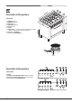
Replacing the nozzles for the hob burners:
1. Remove the hob grids and slide the burners
off their seats.
2. Unscrew the nozzles using a 7 mm socket
spanner (see gure), and replace them with
nozzles suited to the new type of gas (see
Burner and nozzle specications table).
3. Replace all the components by following
the above instructions in reverse.
Replacing the nozzles on separate “double ame “ burners
1. remove the grids and slide the burners from their housings. The burner
consists of 2 separate parts (see gure);
2. unscrew the burers with a 7 mm wrench spanner. The internal burner
has a nozzle, the external burner has two (of the same size). Replace the
nozzle with models suited to the new type of gas (see “Table of burner
and nozzle specications”).
3. replace all the components by repeating the steps in reverse order.