
Operation Manual


GB
! Please keep this instruction booklet in a safe place
for future reference.. Make sure the booklet remains
with the appliance if it is sold, given away or moved.
! Please read this manual carefully: it contains
important information on installation, operation and
safety.
! The appliance must be installed by a qualified
professional in accordance with the instructions
provided.
! Any necessary adjustment or maintenance must be
performed after the cooker has been disconnected
from the electricity supply.
Positioning and levelling
! The appliance may be installed alongside any
cupboards whose height does not exceed that of the
hob surface.
! Make sure that the wall which is in contact with the
back of the appliance is made from a non-
flammable, heat-resistant material (T 90°C).
To install the appliance correctly:
• Place it in the kitchen, the dining room or the
studio flat (not in the bathroom).
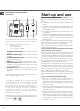
• If the top of the hob is higher than the cupboards,
the appliance must be installed at least 600 mm
away from them.
• If the cooker is installed underneath a wall cabinet,
there must be a minimum distance of 420 mm
between this cabinet and the top of the hob.
This distance should
be increased to 700
mm if the wall cabinets
are flammable (
see
figure
).
• Do not position
blinds behind the
cooker or less than 200
mm away from its
sides.
• Any hoods must be installed in accordance with
the instructions listed in the relevant operating
manual.
Levelling
If it is necessary to level the
appliance, screw the
adjustable feet into the
positions provided on each
corner of the base of the
cooker (
see figure
).
Electrical connection
Installation
HOOD
420
Min.
min.
650
mm. with hood
min.
700
mm. without hood
mm.
600
Min. mm.
420
Min. mm.
3
Electrical connection
Electric cookers come without a power supply cable.
The cooker is designed to operate on an electricity
supply which conforms to the electrical data shown on
the Rating Plate. The cooker can be connected to the
mains only after removing the back panel of the cooker
itself with a screwdriver.
! the following installation procedure must be carried
out by a qualified electrician. The electrical installation
must comply with the IEE Regulations, Building & local
By-Lays.
1. Open the terminal
board by inserting a
screwdriver into the side
tabs of the cover. Use
the screwdriver as a
lever by pushing it down
to open the cover (see
diagram).
2. Loosen the cable clamp
screw and remove it,
using a screwdriver as a
lever (see figure).
3. Remove the wire
contact screws L-N-
, then fasten the wires
under the screw heads,
respecting the colour
code: Black/Blue (N), Red/
Brown (L) and Bare Wire/
Yellow-Green (
).
• Once the connections
have been made, tighten all the terminal screws fully.
• Fasten the supply cable in place with the clamp and
close the cover of the terminal board.