
Instruction for Use


6
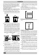
is positioned in or next to the tap pin, until the flame is
small but steady.
N.B.: in the case of liquid gas, the regulation screw
must be screwed in to the bottom.
• check that the flame does not turn off when you turn
the tap quickly from high to low.
d Regulating the primary air of the burners:
The primary air of the burners requires no regulation.
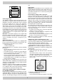
Important
On completion of the operation, replace the old rating
sticker with one indicating the new type of gas used. This
sticker is available from our Service Centres.
Note
Should the pressure of the gas used be different (or vary)
from the recommended pressure, it is necessary to fit a
suitable pressure regulator onto the inlet pipe in
compliance with current National Regulations relative to
“regulators for channelled gas”.
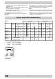
Burner and nozzle characteristics
Table 1 Liquid Gas Natural Gas
Burner Diameter
(mm)
Thermal Power
kW (p.c.s.*)
By-Pass
1/100
Nozzle
1/100
Flow*
g/h
Nozzle
1/100
Flow*
l/h
Nozzle
1/100
Flow*
l/h
Nominal Reduced (mm) (mm) *** ** (mm) (mm)
Fast
(Large)(R)
100 3.00 0.7 41 86 218 214 116 286 143 286
Semi Fast
(Medium)(S)
75 1.90 0.4 30 70 138 136 106 181 105 181
Auxiliary
(Small)(A)
55 1.00 0.4 30 50 73 71 79 95 80 95
Supply
Pressures
Nominal (mbar)
Minimum (mbar)
Maximum (mbar)
28-30
20
35
37
25
45
20
17
25
13
6,5
18
* At 15°C and 1013 mbar- dry gas
** Propane P.C.S. = 50,37 MJ/Kg
*** Butane P.C.S. = 49,47 MJ/Kg
Natural P.C.S. = 37,78 MJ/m
3
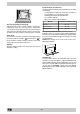
S
S
R
A
K 340 ES/EU