
Instruction for Use

23
GB
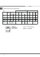
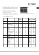
TECHNICAL DATA
Oven dimensions
(HxWxD)
34x39x41 cm
Volume
59 l
Useful
measurements
relating to the oven
compartment
width 42 cm
depth 44 cm
height 23 cm
Power supply voltage
and frequency
see data plate
Energy Label
Declared energy consumption for
Natural convection Class
Heating mode: Convection
Energy consumption for Forced
convection heating mode:
Fan assisted
Burners
may be adapted for use with any
type of gas shown on the data
plate, which is located inside the
flap or, after the oven
compartment has been opened,
on the left-hand wall inside the
oven.
EC Directives: 2006/95/EC dated
12/12/06 (Low Voltage) and
subsequent amendments -
2004/108/EC dated 15/12/04
(Electromagnetic Compatibility)
and subsequent amendments -
2009/142/EC dated 30/11/09
(Gas) and subsequent
amendments - 93/68/EEC dated
22/07/93 and subsequent
amendments - 2002/96/EC.
1275/2008 (Stand-by/ Off mode)
• Fits firmly into place at both ends, where it will
be fixed using clamps that comply with current
regulations.
! If one or more of these conditions is not fulfilled
or if the cooker must be installed according to the
conditions listed for class 2 - subclass 1 appliances
(installed between two cupboards), the flexible steel
hose must be used instead (see below).
Connecting a flexible jointless stainless steel pipe to
a threaded attachment
Make sure that the hose and gaskets comply with
current national legislation.
To begin using the hose, remove the hose holder on the
appliance (the gas supply inlet on the appliance is a
cylindrical threaded 1/2 gas male attachment).
! Perform the connection in such a way that the hose
length does not exceed a maximum of 2 metres,
making sure that the hose is not compressed and does
not come into contact with moving parts.
Checking the connection for leaks
When the installation process is complete, check the
hose fittings for leaks using a soapy solution. Never
use a flame.
Adapting to different types of gas
It is possible to adapt the appliance to a type of gas
other than the default type (this is indicated on the
rating label on the cover).
Adapting the hob
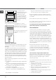
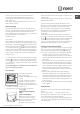
Replacing the nozzles for the
hob burners:
1. Remove the hob grids and
slide the burners off their seats.
2. Unscrew the nozzles using
a 7 mm socket spanner (see
gure), and replace them with
nozzles suited to the new type
of gas(see Burner and nozzle speci cations table).
3. Replace all the components by following the above
instructions in reverse.
Adjusting the hob burners’ minimum setting:
1. Turn the tap to the minimum position.
2. Remove the knob and adjust the regulatory screw,
which is positioned inside or next to the tap pin, until
the flame is small but steady.
! If the appliance is connected to a liquid gas supply,
the regulatory screw must be fastened as tightly as
possible.
3. While the burner is alight, quickly change the position of
the knob from minimum to maximum and vice versa several
times, checking that the flame is not extinguished.
! The hob burners do not require primary air
adjustment.
We recommend cleaning the oven before using it for
the first time, following the instructions provided in the
„Care and maintenance” section.
Data plate, is located inside the flap or, after the oven
compartment has been opened, on the left-hand wall
inside the oven.