
Instruction for Use

3
Connecting the gas
The appliance should be connected to a gas cylinder in
compliance with current directives. On some models the
gas supply can be connected on the left or on the right,
as necessary; to change the connection, reverse the
position of the hose holder with that of the cap and replace
replace the gasket (supplied with the appliance).
Remember to install a pressure regulator on the LPG
cylinder, which complies with current directive.
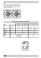
Important: check that the supply pressure complies with
the values indicated in table 1 “Characteristics of the
burners and nozzles” since this will ensure safe operation,
correct consumption and ensure a longer life to your
appliance.
Connection with hose
Make the connection using a gas hose complying with
the the characteristics provided in current directive. The
internal diameter of the pipe used is as follows:
- 8mm for liquid gas;
- 15mm for methane gas.
When installing the hose, remember to take the following
precautions:
• No part of the hose should touch parts whose tempe-
rature exceeds 50°C;
• The length of the hose should be less than 1500 mm;
• The hose should not be subject to twisting or pulling,
and should not have bends or kinks.
• The hose should not touch objects with sharp edges,
any moving parts, and it should not be crushed;
• The full length of the hose should be easy to inspect
in order to check its condition;
Check that the hose fits firmly into place at the two ends
and fix it with clamps complying to current directive.If
any of the above recommendations can not be adopted,
flexible metal pipes should be used.
Should the cooker be installed according to the conditions
of Class 2, subdivision 1, only a flexible metal pipe which
is in compliance with current safety standards should be
used to make the connection to the gas mains.
Connecting a flexible jointless stainless steel pipe
to a threaded attachment
Remove the hose holder fitted on the appliance. The gas
supply pipe fitting is a threaded 1/2 gas cylindrical male
attachment. Only pipes and gaskets complying with
current directives. The full length of the pipe must not
exceed 2000 mm.
Tight control
Important: when installation has been completed, check
the pipe fitting for leaks with a soapy solution. Never use
a flame. Once the connection has been made, ensure that
the flexible metal tube does not touch any moving parts
and is not crushed.
Connecting the supply cable to the mains
Install a normalised plug corresponding to the load
indicated on the data plate. When connecting the cable
directly to the mains, install an omnipolar circuit-breaker
with a minimum contact opening of 3 mm between the
appliance and the mains. The omnipolar circuit breaker
should be sized according to the load and should comply
with current regulations (the earth wire should not be
interrupted by the circuit breaker).
The supply cable should be positioned so that it does not
reach a temperature of more than 50°C with respect to the
room temperature, along its length. Before making the
connection, check that:
• the limiter valve and the home system can support the
appliance load (see data plate);
• the mains is properly earthed in compliance with current
directives and regulations;
• there is easy access to the socket and omnipolar circuit
breaker, once the hob has been installed.
N.B: never use reducers, adaptors or shunts since they
can cause heating or burning.
Adapting the cooker to different types of gas
In order to adapt the cooker to a different type of gas with
respect to the gas for which it was produced (indicated on
the label attached to the lid), follow these steps:
a) replace the hose holder mounted on the appliance with
that supplied in the bag of “cooker accessories”.
• the hose holder for liquid gas is marked 8, the hose
holder for methane gas is marked 13. Always fit the
sealing gasket.
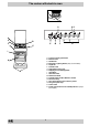
• replacing the burner nozzles on the hob:
• remove the grids and slide the burners from their
housings;
• unscrew the nozzles using a 7 mm socket spanner,
and replace them with nozzles for the new type of gas
(see table 1 “Burner and nozzle characteristics”).
• replace all the components by repeating the steps in
reverse order.
b) Minimum regulation of the hob burners:
•
turn the tap to minimum;
• remove the knob and adjust the regulation screw, which
is positioned in or next to the tap pin, until the flame is
small but steady.
N.B.: in the case of liquid gas, the regulation screw
must be screwed in to the bottom.
• check that the flame does not turn off when you turn
the tap quickly from high to low.
c) Regulating the primary air of the burners:
The primary air of the burners requires no regulation.
Important
On completion of the operation, replace the old rating
sticker with one indicating the new type of gas used. This
sticker is available from our Service Centres.
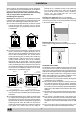
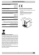
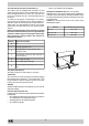
HOOD
420
Min.
min.
650
mm. with hood
min.
700
mm. without hood
mm.
600
Min. mm.
420
Min. mm.