PL 640 SP TK/HA PL 640 S /HA Polski Instrukcja obsługi PŁYTA Spis treści Instrukcja obsługi,1 Ostrzezenia,2 Serwis Techniczny,3 Opis urządzenia,5 Instalacja,18 Uruchomienie i użytkowanie,22 Zalecenia i środki ostrożności,22 Konserwacja i utrzymanie,23 Anomalie i środki zaradcze,23 Italiano Türkçe Istruzioni per l’uso PIANO Sommario Istruzioni per l’uso,1 Avvertenze,2 Assistenza,3 Descrizione dell’apparecchio,4 Installazione,6 Avvio e utilizzo,10 Precauzioni e consigli,10 Manutenzione e cura,11 Anomal
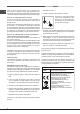
Avvertenze ATTENZIONE: l’uso di protezioni del piano inappropriate può causare incidenti. Warnings CAUTION: the use of inappropriate hob guards can cause accidents. Ostrzezenia U WA G A : u ż y c i e n i e w ł a ś c i w y c h zabezpieczeń płyty może być przyczyną wypadków. Uyarı D İ K K AT: u y g u n o l m a y a n o c a k koruyucularının kullanılması, kazalara neden olabilir.
Assistenza Comunicare: • il tipo di anomalia • il modello della macchina (Mod.) • il numero di serie (S/N) Queste ultime informazioni si trovano sulla targhetta caratteristiche posta sull’apparecchio. Assistance Communicating: • appliance model (Mod.) • serial number (S/N) This information is found on the data plate located on the appliance and/or on the packaging. Non ricorrete mai a tecnici non autorizzati e rifiutate sempre l’installazione di pezzi di ricambio non originali.
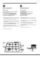
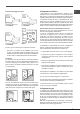
Descrizione dell’apparecchio Description of the appliance Vista d’insieme Overall view 1 2 3 4 5 6 1 2 3 4 5 6 Griglie di appoggio per RECIPIENTI DI COTTURA BRUCIATORI GAS Manopole di comando dei BRUCIATORI GAS Pulsante di accensione dei BRUCIATORI GAS* Candela di accensione dei BRUCIATORI GAS* DISPOSITIVO DI SICUREZZA* Support Grid for COOKWARE GAS BURNERS Control Knobs for GAS BURNERS GAS BURNERS button* Ignition for GAS BURNERS* SAFETY DEVICES* • BRUCIATORI GAS sono di diverse dimensioni e potenze.
Opis urządzenia Cihazın tanıtımı Widok ogólny Genel görünüm 1 2 3 4 5 6 1 2 3 4 5 6 Kratki do ustawiania NACZYŃ DO GOTOWANIA PALNIKI GAZOWE Pokrętła sterujące PALNIKÓW GAZOWYCH Pokrętła sterujące PALNIKÓW GAZOWYCH* Świeca zapłonowa PALNIKÓW GAZOWYCH* URZĄDZENIA ZABEZPIECZAJĄCE* • PALNIKI GAZOWE posiadają różne wymiary i moce. Należy wybrać ten palnik, który jest najbardziej odpowiedni dla średnicy używanego naczynia.
! È importante conservare questo libretto per poterlo consultare in ogni momento. In caso di vendita, di cessione o di trasloco, assicurarsi che resti insieme all’apparecchio per informare il nuovo proprietario sul funzionamento e sui relativi avvertimenti. ! Leggere attentamente le istruzioni: ci sono importanti informazioni sull’installazione, sull’uso e sulla sicurezza.
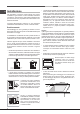
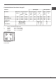
30 20 Posizione gancio per top H=20mm Posizione gancio per top H=30mm Avanti Dietro ! Usare i ganci contenuti nella “confezione accessori” • Nel caso in cui il piano non sia installato su di un forno incasso, è necessario inserire un pannello di legno come isolamento. Esso dovrà essere posizionato ad una distanza minima di 20 mm. dalla parte inferiore del piano stesso. Aerazione Per garantire una buona aerazione è necessario eliminare la parete posteriore del vano.
IT ! Per un sicuro funzionamento, per un adeguato uso dell’energia e maggiore durata dell’apparecchiatura, assicurarsi che la pressione di alimentazione rispetti i valori indicati nella tabella 1 “Caratteristiche dei bruciatori ed ugelli”. Allaccio con tubo rigido (rame o acciaio) ! L’allaccio all’impianto gas deve essere effettuato in modo da non provocare sollecitazioni di alcun genere all’apparecchio.
Caratteristiche dei bruciatori ed ugelli IT Tabella 1 Gas liquido Bruciatore Diametro (mm) Potenza termica kW (p.c.s.*) By-Pass ugello 1/100 1/100 Gas naturale portata* g/h ugello 1/100 Nomin. Ridot.
IT Avvio e utilizzo Precauzioni e consigli ! Su ciascuna manopola è indicata la posizione del bruciatore gas o della piastra elettrica* corrispondente. ! L’apparecchio è stato progettato e costruito in conformità alle norme internazionali di sicurezza. Queste avvertenze sono fornite per ragioni di sicurezza e devono essere lette attentamente.
• L’apparecchio non è destinato a essere messo in funzione per mezzo di un temporizzatore esterno oppure di un sistema di comando a distanza separato. Manutenzione rubinetti gas Smaltimento ! Questa operazione deve essere effettuata da un tecnico autorizzato dal costruttore. • Smaltimento del materiale di imballaggio: attenersi alle norme locali, così gli imballaggi potranno essere riutilizzati.
Installation Positioning • Liquid petroleum gas sinks to the floor as it is heavier than air. Therefore, rooms containing LPG cylinders must also be equipped with vents to allow gas to escape in the event of a leak. As a result LPG cylinders, whether partially or completely full, must not be installed or stored in rooms or storage areas that are below ground level (cellars, etc.).
Electrical connection Hooking position for top H=20mm 30 20 Hook fastening diagram Hooking position for top H=30mm Front Connecting the supply cable to the mains Install a standardised plug corresponding to the load indicated on the data plate. The appliance must be directly connected to the mains using an omnipolar circuit-breaker with a minimum contact opening of 3 mm installed between the appliance and the mains.
GB ! Check that the pressure of the gas supply is consistent with the values indicated in Table 1 (“Burner and nozzle specifications”). This will ensure the safe operation and longevity of your appliance while maintaining efficient energy consumption. Connection with a rigid pipe (copper or steel) ! Connection to the gas system must be carried out in such a way as not to place any strain of any kind on the appliance.
Burner and nozzle specifications GB Table 1 Natural Gas Liquid Gas Burner Diameter (mm) Thermal power kW (p.c.s.*) By-Pass 1/100 Nozzle 1/100 Flow* g/h Nozzle 1/100 Nomin. Ridot.
GB Start-up and use Precautions and tips ! The position of the corresponding gas burner or electric hotplate* is shown on every knob. ! This appliance has been designed and manufactured in compliance with international safety standards. The following warnings are provided for safety reasons and must be read carefully.
• Do not let children play with the appliance. • IMPORTANT SAFETY INFORMATION FOR UK MARKET: Please note that this product is not fitted with a flame supervision device. It is NOT suitable for fitting or use in high rise flats or multiple dwellings. If you are in any doubt please contact a CORGI registered gas engineer for advice. • The appliance is not intended to be operated by means of an external timer or separate remote-control system.
Ustawienie ! Opakowania nie są zabawkami dla dzieci i należy je usunąć zgodnie z normami zbierania odpadów (patrz Środki ostrożności i zalecenia). ! Instalacja powinna zostać wykonana zgodnie z niniejszymi instrukcjami i przez personel zawodowo do tego przygotowany. Błędna instalacja może skutkować powstaniem szkód wobec osób, zwierząt lub rzeczy. ! Niniejsze urządzenie może zostać zainstalowane wyłącznie w pomieszczeniach ze stałą wentylacją, zgodnie z zaleceniami obowiązujących norm krajowych.
Podłączenie do sieci elektrycznej Położenie uchwytu w stosunku do top H=20mm 30 20 Schemat mocowania uchwytów Położenie uchwytu w stosunku do top H=30mm Przód Podłączenie przewodu zasilającego do sieci Zamocować na przewodzie znormalizowaną wtyczkę do obciążeń wskazanych na tabliczce znamionowej.
PL ! W celu uzyskania pewności pracy, odpowiedniego zużycia energii i zwiększenia trwałości urządzenia należy upewnić się czy ciśnienie zasilania mieści się w granicach zalecanych w tabeli 1 „Charakterystyki palników i dysz”. Podłączenie przewodem sztywnym (miedź lub stal) ! Podłączenie do urządzenia gazowego powinno być wykonane w taki sposób, aby nie powodować żądnych naprężeń urządzenia.
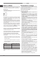
Charakterystyki palników oraz dysz Tabela 1 (dla Polski) Palnik Ś rednica Moc cieplna By-pass (w mm) (p.c.s.*) 1/100 kW (w mm) Min. Mak. Duż y (R) 100 0.75 3.00 39 Półszybki (ś redni) (S) 75 0.40 1.90 28 Pomocniczy (mały) (A) 55 0.40 1.00 28 minimalne (mbar) Ciś nienia zasilania nominalne (mbar) maksymalne (mbar) PL G 20 Dysza Przepływ* 1/100 l/godz (w mm) 116 (Y) 106 (6) 79 (6) 17 20 25 286 181 95 G 30 Dysza Przepływ* 1/100 l/godz (w mm) 80 65 48 25 37 45 218 138 73 G 2.350 Moc cieplna Dysza (p.c.
PL Uruchomienie i użytkowanie Zalecenia i środki ostrożności ! Dla każdego z pokręteł wskazane jest położenie palnika gazowego lub płyty elektrycznej* odpowiadających im.
• Nie jest przewidziane aby urządzenie było używane przez osoby (również dzieci) niesprawne fizycznie i umysłowo, przez osoby bez doświadczenia lub bez znajomości urządzenia chyba, ze pod nadzorem osoby odpowiedzialnej za jego bezpieczeństwo jak również bez otrzymania instrukcji wstępnych co do jego użytku. • Urządzenie nie jest przeznaczone do tego, aby było włączane przy użyciu zewnętrznego przekaźnika czasowego lub osobnego systemu sterowania zdalnego.
! Her gerektiğinde başvurulabilmesi için bu el kitapçığının muhafaza edilmesi önemlidir. Cihazın satılması, başkasına verilmesi ya da taşınması durumunda yeni kullanıcının işleyiş ve ilişkin uyarılar hakkında bilgi edinmesi için el kitapçığının cihazla birlikte verildiğinden emin olunuz. ! Talimatları dikkatli bir şekilde okuyunuz: kurulum, kullanım ve emniyet hakkında önemli bilgiler içermektedir.
Kanca sabitleme şeması TR 30 20 Elektrik bağlantısı Çalışma tezgahı için Çalışma tezgahı için kanca pozisyonu H=20mm kanca pozisyonu H=30mm Ön taraf 40 Besleme kablosunun şebekeye bağlantısı Kabloya özellikler etiketi üzerinde belirtilen yüke uygun bir fiş monte ediniz.
TR ! Emniyetli bir çalışma, uygun enerji kullanımı ve cihazın ömrünün uzun olması için, besleme basıncının tablo 1 “Brülör ve memelerin özellikleri”nde gösterilen değerler arasında olduğundan emin olunuz. Sert bir boru ile bağlantı (bakır ya da çelik) ! Gaz tesisatına bağlantı cihazda hiçbir türden zorlama yaratmayacak şekilde gerçekleştirilmelidir. Cihazın besleme rampası üzerinde, yönlendirilebilir bir “L” rakoru bulunmaktadır, bunun sızdırmazlığı da bir conta ile sağlanmıştır.
Brülör ve memelerin özellikleri TR Çizelge 1 Sıvı gaz Ocak Çap (mm) Termik güç kW (p.c.s.*) Nominal Azaltılmış By-pass 1/100 (mm) Meme 1/100 Doğal gaz Tasima gücü* l/saat Meme 1/100 (mm) *** ** (mm) Tasima gücü* l/saat Hızlı (R) 100 3.00 0.70 39 86 218 214 116 286 Yarı Hızlı (S) 75 1.90 0.40 28 70 138 136 106 181 Yardımcı (A) 55 1.00 0.
TR Başlatma ve kullanım Önlemler ve tavsiyeler ! Her bir düğme üzerinde kumanda ettiği gaz brülörünün ya da elektrikli levhanın* konumu belirtilmiştir. ! Cihaz uluslararası emniyet mevzuatlarına uygun olarak projelendirilmiş ve üretilmiştir. Bu uyarılar güvenlik amaçlı olup dikkatlice okunmalıdır.
toplanması gerekir. Tüm ürünlerin üzerinde; ayrıştırılmış atık hükümlerini hatırlatmak amacıyla üstünde çarpı işareti olan sepet sembolü yer almaktadır. Kullanılmayan beyaz eşyalar belediye atık toplama servisine teslim edilebilecektir, bunları belediyenin bunun için özel olarak belirlediği yerlere ya da konuyla ilgili ulusal düzenlemelerin mevcut olduğu durumlarda, benzer tipte yeni bir ürün aldığınız satıcılara verebilirsiniz.
TR 30
TR 31
195088514.