
Instruction for Use

24
GB
been carried out, make sure that the exible metal pipe
does not touch any moving parts and is not compressed.
! Only use pipes and seals that comply with current national
regulations.
Checking the tightness of the connection
! When the installation process is complete, check the pipe
ttings for leaks using a soapy solution. Never use a ame.
Adapting to different types of gas
To adapt the hob to a different type of gas other than default
type (indicated on the rating plate at the base of the hob or
on the packaging), the burner nozzles should be replaced
as follows:
1. Remove the hob grids and slide the burners off their
seats.
2. Unscrew the nozzles using a 7 mm socket spanner, and
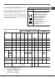
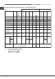
replace them with nozzles for the new type of gas (see
table 1 “Burner and nozzle characteristics”).
3. Reassemble the parts following the above procedure in
the reverse order.
4. Once this procedure is nished, replace the old rating
sticker with one indicating the new type of gas used.
Sticker are available from any of our Service Centres.
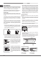
Replacing the nozzles on separate “double ame “
burners
1. remove the grids and slide the burners from their
housings. The burner consists of 2 separate parts (see
gure);
2. unscrew the burers with a 7 mm wrench spanner. The
internal burner has a nozzle, the external burner has
two (of the same size). Replace the nozzle with models
suited to the new type of gas (see table 1).
3. replace all the components by repeating the steps in
reverse order.
Replacing the Triple ring burner nozzles
1. Remove the pan supports and lift the burners out of their
housing. The burner consists of two separate parts (see
pictures).
2. Unscrew the nozzles using a 7 mm socket spanner.
Replace the nozzles with models that are congured
for use with the new type of gas (see Table 1). The two
nozzles have the same hole diameter.
3. Replace all the components by completing the above
operations in reverse order.
• Adjusting the burners’ primary air
Does not require adjusting.
• Setting the burners to minimum
1. Turn the tap to the low ame position;
2. Remove the knob and adjust the adjustment screw, which
is positioned in or next to the tap pin, until the ame is
small but steady.
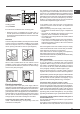
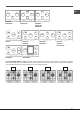
! In the event of single-control DRDA (DCDR) burners,
adjustment can be performed by intervening on the 2 screws
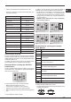
located near the tap pin (see picture).
Inner DRDA (DCDR)
burner adjustment
Total DRDA
(DCDR) burner
adjustment
3. Having adjusted the ame to the required low setting,
while the burner is alight, quickly change the position
of the knob from minimum to maximum and vice versa
several times, checking that the ame does not go out.
4. Some appliances have a safety device (thermocouple)
tted. If the device fails to work when the burners are set
to the low ame setting, increase this low ame setting
using the adjusting screw.
5. Once the adjustment has been made, replace the
seals on the by-passes using sealing wax or a similar
substance.
6. In the event of discrete-adjustment knobs with LED
visualisation, turn the knob to the minimum power setting
them remove it and intervene on the adjustment screw
located near the tap pin.
7. Minimum setting adjustment of the DRDA (DCDR) burner
with discrete adjustment and LED visualisation:
• To adjust the outer ring, turn the knob anti-clockwise
to the minimum power position.
• To adjust the minimum power setting of the inner ring,
turn the knob clockwise to the minimum power position.
• Remove the knob and intervene on the adjustment
screw located near the tap pin.