
Instruction for Use


6
GB
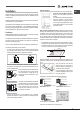
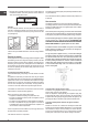
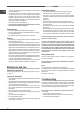
• Where the hob is not installed over a built-in oven, a wooden panel must
be installed as insulation. This must be placed at a minimum distance of
40 mm from the lower part of the hob.
min. 40 mm
100 mm
Ventilation
To ensure adequate ventilation, the back panel of the cabinet must be
removed. It is advisable to install the oven so that it rests on two strips of
wood, or on a completely at surface with an opening of at least 45 x 560
mm (see diagrams).
560 mm.
45 mm.
! The hob can only be installed above built-in ovens with a cooling ventilation
system.
Electrical connection
Hobs equipped with a three-pole power supply cable are designed to operate
with alternating current at the voltage and frequency indicated on the data
plate (this is located on the lower part of the appliance). The earth wire in the
cable has a green and yellow cover. If the appliance is to be installed above
a built-in electric oven, the electrical connection of the hob and the oven must
be carried out separately, both for electrical safety purposes and to make
extracting the oven easier.
Connecting the supply cable to the mains
Install a standardised plug corresponding to the load indicated on the data
plate.
The appliance must be directly connected to the mains using an omnipolar
circuit-breaker with a minimum contact opening of 3 mm installed between the
appliance and the mains. The circuit-breaker must be suitable for the charge
indicated and must comply with current electrical regulations (the earthing
wire must not be interrupted by the circuit-breaker). The supply cable must
not come into contact with surfaces with temperatures higher than 50°C.
! The installer must ensure that the correct electrical connection has been
made and that it is compliant with safety regulations.
Before connecting to the power supply, make sure that:
• the appliance is earthed and the plug is compliant with the law.
• the socket can withstand the maximum power of the appliance, which is
indicated on the data plate.
• the voltage is in the range between the values indicated on the data plate.
• the socket is compatible with the plug of the appliance. If the socket is
incompatible with the plug, ask an authorised technician to replace it. Do
not use extension cords or multiple sockets.
! Once the appliance has been installed, the power supply cable and the
electrical socket must be easily accessible.
! The cable must not be bent or compressed.
! The cable must be checked regularly and replaced by authorised technicians
only (see Assistance).
! The manufacturer declines any liability should these safety measures not
be observed.
Gas connection
This appliance is suitable for connection with rigid pipe or exible hose.
The isolating manual shut-off valve connection point must be accessible when
appliance is installed. Natural Gas: the supplied regulator must be tted to
the appliance inlet connection.
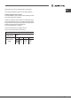
! Check that the pressure of the gas supply is consistent with the values indicated
in Table 1 (“Burner and nozzle specications”). This will ensure the safe operation
and longevity of your appliance while maintaining efcient energy consumption.
! For NG models the gas supply is connected to a regulator which is supplied.
The inlet connection has ½” B.S.P female thread. IT IS ESSENTIAL THAT
THE ELBOW ON THE APPLIANCE BE HELD FIRMLY WITH A SPANNER.
DO NOT OVER TIGHTEN. The regulated pressure for NG is 1.00kPa.
! A manual shut-off valve must be installed in the gas line, in an accessible
position external to the hotplate, so that in the event of an emergency or
service,the gas supply can be shutoff.
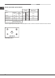
! For gas inlet position of appliance refer Fig. 1 for NG. After installing the
gas supply and making all connections check thoroughly for possible leaks.
Turn all control knobs on the unit to “OFF” position. Open the valve on the
gas supply. Using a soap and water solution check each gas connection one
at a time, by brushing the solution over connection. Presence of bubbles will
indicate a leak. Tighten the tting and re-check for leaks. If it is not possible
to correct the leak, replace tting. Under no circumstance use matches or
ame for checking leaks.
Fig. 1
Connection with a rigid pipe (copper or steel)
! Connection to the gas system must be carried out in such a way as not to
place any strain of any kind on the appliance.
There is an adjustable L-shaped pipe tting on the appliance supply ramp
and this is tted with a seal in order to prevent leaks. The seal must always
be replaced after rotating the pipe tting (seal provided with appliance). The
gas supply pipe tting is a threaded 1/2 gas cylindrical male attachment.
Connecting a exible jointless stainless steel pipe to a threaded
attachment
Suitable for connection with a exible hose assembly.The exible hose
assembly must be certied to AS/NZS 1869 class B or D, be of appropriate
internal diameter, be kept as short as possible (not to exceed 1200 mm),
must not be in contact with the oor or any hot or sharp surfaces. The hose
assembly must not be subject to strain, abrasion, kinking or deformation.