
Instruction for Use


GB
7
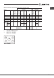
Table 1 Liquid Gas Natural Gas
Burner Diameter Thermal Thermal By-pass Nozzle Flow* Thermal Nozzle Flow*
power power 1/100 1/100 (g/h) power 1/100 (l/h)
kW kW kW
(p.c.s.*) (p.c.s.*) (p.c.s.*)
(mm) Reduced Nominal (mm) (mm) *** ** Nominal (mm)
Supply pressures Nominal (mbar)
Minimum (mbar)
Maximum (mbar)
28-30
20
35
37
25
45
20
17
25
Reduced Rapid (RR)
Semi Rapid (S)
Auxiliary (A)
100
75
55
36
130
0.70
0.40
0.40
0.30
1.50
2.60
1.65
1.00
0.90
4.20
39
28
28
29
29
57
80
64
50
44
44
67x2
189
120
73
65
305
186
118
71
64
300
2.60
1.65
1.00
0.90
4.20
122 (H3)
96 (Z)
79 (6)
74
74
100x2
248
157
95
86
400
Double flame
(DCDR internal) (1)
Double
flame (1)
(DCDR
internal)
(DCDR
external
2 nozzle)
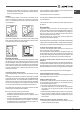
Burner and nozzle specifications (for 75 cm versions only)
(1) For single-control DRDA (DCDR) burner only
* At 15°C and 1013,25 mbar - dry gas
** Propane P. C.S. = 50.37 MJ/Kg
*** Butane P.C.S. = 49.47 MJ/Kg
Natural P. C.S. = 37.78 MJ/m³
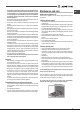
RR
DC
S
S
A
PKLL 751 D2/IX/A