
Instruction for Use


GB
17
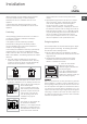
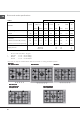
2.5 mm
R 11
862 mm
838 mm
512 mm
488 mm
FOR MOD: PPF QFOR MOD: PPF Q
FOR MOD: PPF QFOR MOD: PPF Q
FOR MOD: PPF Q
Fig.4b
845 mm
495 mm
FOR MOD: PP QFOR MOD: PP Q
FOR MOD: PP QFOR MOD: PP Q
FOR MOD: PP Q
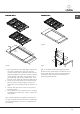
N.B.: An insulating wooden panel should be fitted
beneath the hob, positioned at a minimum of 20 mm
from the hob underside. This wooden panel must be
removable in order to allow for any maintenance
operations beneath the hob.
X mm
X mm
Fig.5Fig.4a
3- Sit-on hobs (Class 1) with edges higher than 58 mm
(see figure 2, detail H3). In this case, the lower
casing of the hob does not protrude further than the
edge of the appliance. Even when the hob is resting
on the worktop, it will suffice to leave space for the
gas supply tube and electricity supply cable. To fit
this type of hob, follow the instructions below (fig. 5):
• Fix the two screws provided "A" at a distance from
the back panel as shown in figure 5, leaving the
heads of the screws sticking out of the wood by 1.5
mm.
• Hook the hob onto the two screws "A" and push it
towards the back.
• Fix the appliance to the cabinet at the rear, using the
two brackets "B" and the four screws "C" (these are
all provided).
N.B.: to make maintenance operations more efficient,
the area around the hob must be easily accessible after
it has been installed (i.e. there are no completely shut-
off elements).