Operator Manual Manuel de l’opérateur Manual del operador 200-2700 Revision C Belt Drive, Electric Air Compressors TOPS™ - Thermal Overload Protection System NOTE: These units DO NOT require a magnetic starter. Actionnement pour courroie, Compresseur d’air électrique TOPS™ - Dispositif de protection contre la surcharge thermique REMARQUE : Ces compresseurs ne nécessitent pas l’installation d’un démarreur magnétique.
TABLE OF CONTENTS / TABLE DES MATIÈRES / ÍNDICE TABLE OF CONTENTS SAFETY GUIDELINES . . . . . . . . . . . . . . . . . . . . . . . . . . .3 OVERVIEW . . . . . . . . . . . . . . . . . . . . . . . . . . . . . . . . . . .6 Basic Air Compressor Components . . . . . . . . . . . . .6 ASSEMBLY . . . . . . . . . . . . . . . . . . . . . . . . . . . . . . . . . . .7 Assembling Of The Compressor . . . . . . . . . . . . . . . .7 Typical Installation . . . . . . . . . . . . . . . . . . . . . . . .
SAFETY GUIDELINES The following information relates to protecting YOUR SAFETY and PREVENTING EQUIPMENT PROBLEMS. To help you recognize this information, we use the following symbols. Please read the manual and pay attention to these sections. DANGER: – A POTENTIAL HAZARD THAT WILL CAUSE SERIOUS INJURY OR LOSS OF LIFE. WARNING: – A POTENTIAL HAZARD THAT COULD CAUSE SERIOUS INJURY OR LOSS OF LIFE. CAUTION: – A POTENTIAL HAZARD THAT MAY CAUSE MODERATE INJURY OR DAMAGE TO EQUIPMENT. WARNING 1. 2. 3. 4. 5.
CONSIGNES DE SÉCURITÉ Les informations suivantes concernent VOTRE SÉCURITÉ et LA PROTECTION DU MATÉRIEL CONTRE LES PANNES. Pour vous aider à identifier la nature de ces informations, nous utilisons les symboles suivants. Veuillez lire le manuel et prêter attention à ces sections. DANGER: – DANGER POTENTIEL POUVANT ENTRAÎNER DE GRAVES BLESSURES OU LA MORT. AVERTISSEMENT: – DANGER POUVANT CAUSER DES BLESSURES GRAVES VOIRE MORTELLES.
PAUTAS DE SEGURIDAD La información que sigue se refiere a la protección de SU SEGURIDAD y la PREVENCIÓN DE PROBLEMAS DEL EQUIPO. Como ayuda para reconocer esta información, usamos los siguientes símbolos. Lea por favor el manual y preste atención a estas secciones. PELIGRO: - UN POSIBLE RIESGO QUE CAUSARÁ LESIONES GRAVES O LA PÉRDIDA DE LA VIDA. ADVERTENCIA: - UN RIESGO POTENCIAL QUE PODRÍA PROVOCAR GRAVES LESIONES O MUERTE.
OVERVIEW / VUE D’ENSEMBLE / RESUMEN GENERAL BASIC AIR COMPRESSOR COMPONENTS The basic components of the air compressor are the electric motor, Thermal Overload Protection System (TOPS), pump, and receiver (tank). The tank may be vertical or horizontal, varying in size and capacity. The electric motor (see A) powers the pump. TOPS senses both temperature and current, providing more complete motor overload protection than a magnetic starter, which senses only current.
ASSEMBLY / ASSEMBLAGE ASSEMBLING THE COMPRESSOR 1. compresseur d’air manuel de l’opérateur et manuel de pièces Unpack the air compressor. Inspect the unit for damage. If the unit has been damaged in transit, contact the carrier and complete a damage claim. Do this immediately because there are time limitations to damage claims. 2.
ASSEMBLAGE / MONTAJE ASSEMBLAGE DU COMPRESSEUR b. c. d. Le compresseur doit être situé à au moins 30 cm de tout mur ou obstacle, dans un endroit propre et bien ventilé, afin d'assurer une circulation d'air et un refroidissement adéquats. Dans les zones climatiques froides, placez le compresseur dans un bâtiment chauffé pour minimiser les problèmes de graissage, de mise en marche du moteur et de gel de la condensation de l’eau.
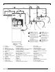
TYPICAL INSTALLATION / INSTALLATION TYPIQUE / INSTALACION TIPICA A B C D E F G H J K L M N P R T U WARNING: Risk of bursting, resulting in injury. Never use Plastic pipe for compressed air. CAUTION: Never use lubricator for paint spraying or similar applications. ADVERTISSEMENT : Risque d’éclatement pouvant entraîner des blessures. N’utilisez jamais de tuyau en plastique pour de l’air comprimé.
TYPICAL INSTALLATION / INSTALLATION TYPIQUE / INSTALACION TIPICA TYPICAL INSTALLATION INSTALACION TIPICA Air dryers and after coolers An air dryer or aftercooler is installed directly in the air line. Secadores de aire y post–enfriadores El secador de aire o el radiador de alida se instalan directamente en la línea de aire. Moisture removal and air filtration As the air cools, moisture will condense in the lines. This moisture must be removed before it reaches the tool being used.
COMPRESSOR CONTROLS / COMMANDES DU COMPRESSEUR COMPRESSOR CONTROLS Main Power Disconnect Install a main power disconnect switch in the power line to the compressor, near the compressor’s location. It is operated manually, but when it is in the ON position, the compressor will start up or shut down automatically based on air demand. ALWAYS operate this switch to OFF when the compressor is not being used.
CONTROLES DEL COMPRESOR Soupape de décharge (voir B) Si le manostat n'arrête pas le moteur quand la pression atteint le niveau prédéfini, cette soupape s'ouvre automatiquement pour éviter toute surpressurisation. Pour l'actionner manuellement, tirez sur son anneau afín de libérer la pression d'air dans le réservoir. Manomètre du réservoir (voir C) Ce manomètre mesure le niveau de pression d'air dans le réservoir. L'utilisateur ne peut pas régler ce manomètre et il n'indique pas la pression dans la conduite.
ELECTRICAL POWER REQUIREMENTS / SPÉCIFICATIONS DU COURANT ÉLECTRIQUES ELECTRICAL WIRING Refer to the air compressor’s serial label for the unit’s voltage and amperage requirements. Ensure that all wiring is done by a licensed electrician, in accordance with the National Electrical Code. Use electrical conduit to protect the wiring. MAIN POWER PANEL For best performance and reliable starting, the air compressor must be installed on a dedicated circuit, as close as possible to the electrical power panel.
REQUERIMIENTOS DE ALIMENTACION ELECTRICA CABLEADO ELECTRICO Refiérase al rótulo del número de serie del compresor de aire para conocer los requerimientos de voltaje y amperaje de la unidad. Cerciórese de que todo el cableado lo instala un electicista capacitado, de conformidad con el Código Eléctrico Nacional. Use tubo eléctrico para proteger los cables.
BREAK-IN OF THE PUMP / RODAGE DE LA POMPE / MARCHA INICIAL DE LA BOMBA BREAK-IN OF THE PUMP NOTE: The pump is shipped with break-in oil which should be changed after the first 8 hours of operation. 1. Check the level of oil in the pump with the sight glass. The pump oil level must be between A and B. Do not overfill or underfill. 2. Make sure the power is connected at the power panel. 3. Open the petcock (see C). 4. Turn ON the main power disconnect switch.
OPERATING INSTRUCTIONS / MODE D’EMPLO 1. 2. 3. 4. DAILY STARTUP Every day check the sight glass to ensure that the level of oil in the pump is at the required level. Make sure the main power disconnect switch is shut OFF. Close the tank petcock (see D). Turn ON the main power disconnect switch. Turn the pressure switch to the ON position (see E). The pump will start filling the tank with air.
MODE D’EMPLO / INSTRUCCIONES OPERATIVAS 1. 2. 3. ARRÊT Placer le manocontacteur en position ARRÊT (voir F). Mettez le sectionneur de tension principale HORS TENSION. Réduisez la pression du réservoir par l’orifice de sortie du tuyau. Vous pouvez également tirer sur l’anneau de la soupape de décharge (voir G) et maintenir la soupape en position ouvert pour libérer la pression du réservoir. PRECAUCIÓN: El aire y la humedad que escapan del tanque pueden arrojar desechos que podrían causarle daño en los ojos.
PUMP LUBRICATION / LUBRIFICATION DE LA POMPE / LUBRICACION DE LA BOMBA OIL LEVEL Always operate the unit in a level position. Prior to start–up, check the sight glass to ensure that the oil in the pump is at the required level. The pump oil level must be between A and B. If the oil level is too low, remove the oil fill plug and add oil until the sight glass shows the correct level. Do not overfill or underfill; too much or too little oil will harm the pump.
MAINTENANCE / ENTRETIEN / MANTENIMIENTO MAINTENANCE WARNING: To avoid personal injury, always shut off the compressor and relieve all air pressure from the system before performing any service on the air compressor. Regular maintenance will ensure trouble–free operation. Your electric powered air compressor represents high–quality engineering and construction; however, even high–quality machinery requires periodic maintenance.
MAINTENANCE / ENTRETIEN / MANTENIMIENTO BELT TENSION AND PULLEY ALIGNMENT WARNING: To avoid personal injury, always shut off the compressor and relieve all air pressure from the system before performing any service on the air compressor. NOTE: Drive belt tensioning and pulley alignment are done at the same time. They are discussed separately for clarity. ADJUSTING DRIVE BELT TENSION Proper belt tension and pulley alignment must be maintained for maximum drive efficiency and belt life.
MAINTENANCE / ENTRETIEN / MANTENIMIENTO PULLEY ALIGNMENT To check pulley alignment, remove the belt guard and place a straightedge (see A) against the pump flywheel (see B). Measure and record the distance from the straightedge to the edge of the drive belt at point C. Then measure the distance from the straightedge to the edge of the drive belt again at points D and E. Both distances should be the same as at point C.
MAINTENANCE / ENTRETIEN / MANTENIMIENTO CLEANING THE AIR FILTER A dirty air filter will reduce the compressor’s performance and life. To avoid any internal contamination of the pump, the filter should be cleaned frequently, and replaced on a regular basis. Felt filters should be cleaned in warm, soapy water, rinsed, and allowed to air dry before reinstallation. Paper filters should be replaced when dirty. Do not allow the filter to become filled with dirt or paint.
SERVICE INTERVAL Perform the following maintenance at the intervals indicated below. Inspect and clean air filter . . . . . . . . . . . . . . . . . . . . . . . . . . . . . . . . . . . . . . . . . . . . .Weekly Check pump oil level . . . . . . . . . . . . . . . . . . . . . . . . . . . . . . . . . . . . . . . . . . . . . . . . . . .Daily Change pump oil . . . . . . . . . . . . . . . . . . . . . . . . . . . . . . . . . . . .Every 200 operating hours . . . . . . . . . . . . . . . . . . . . . . . . . . . . . . .
TROUBLESHOOTING CHART Note: Troubleshooting problems may have similar causes and solutions. PROBLEM POSSIBLE CAUSE SOLUTION Excessive current draw trips circuit breaker Low voltage/motor overload Check that power supply is adequate and that compressor is on a dedicated circuit. Drive belt too tight Readjust belt tension. Restricted air passages Inspect and replace transfer tubes or check valve, as required. Low voltage to motor Furnish adequate power. Bad check valve Replace the check valve.
DÉPANNAGE Remarque : Les problémes de dépannage peuvent avoir des causes et des solutions similaires. PROBLÈME CAUSE POSSIBLE SOLUTION Le prélèvement excessif de courant cause le déclenchement du disjoncteur Tension insuffisante/surcharge du moteur Vérifiez que l’alimentation est adéquate et que le compresseur est branché sur un circuit séparé. Vérifiez que le compresseur est branché sur son propre circuit. Courroie d’entraînement trop serrée Réajustez la tension de la courroie.
CUADRO DE DETECCIÓN DE FALLOS Nota: Los problemas de detección de fallos pueden tener causas y soluciones similares. PROBLEMA CAUSA POSIBLE SOLUCION Una extracción excesiva de la corriente hace saltar el cortacircuito Voltaje bajo/sobrecarga del motor Verifique que el suministro de energía sea el adecuado y que el compresor se encuentre en un circuito exclusivo. Correa de transmisión demasiado ajustada Vuelva a ajustar la tensión de la correa.
GLOSSARY OF TERMS CFM Cubic feet per minute; a unit of measure of air flow. PSI Pounds per square inch; a unit of measure of air pressure. Kick-in pressure Factory set low pressure point that starts the compressor to repressurize the tank to a higher pressure. Kick-out pressure Factory set high pressure point that stops the compressor from increasing the pressure in the tank above a certain level. Well-ventilated A means of providing fresh air in exchange for dangerous exhaust or vapors.
PARTS AND SERVICE Replacement parts and service are available from your nearest authorized Service Center. If the need arises, contact Product Service as listed at right. When needing service, please contact the nearest authorized Service Center or call: When consulting with a Service Center or Product Service, refer to the model number and serial number located on the serial label of the compressor. Proof of purchase is required for all transactions and a copy of your sales receipt may be requested.