IDS 430/433 Weight Indicator Installation/Calibration/Operation Version 1.B 06/13/08 Industrial Data Systems, Inc. 3822 E. La Palma Ave. Anaheim Ca. 92807 Tech Support 714-921-1353 Website: www.industrialdata.com Email: Sales@industrialdata.
TABLE OF CONTENTS INTRODUCTION 6 7 8 GENERAL DESCRIPTION 9 9 10 10 INSTALLATION AND SETUP 11 11 11 13 14 USING THE IDS 430 15 15 16 16 16 16 BUILT IN APPLICATION PROGRAMS 17 17 18 19 20 22 23 24 26 SET OPERATION PARAMETERS 27 27 28 31 31 31 31 32 32 32 32 32 33 33 33 33 33 34 What’s in each section Warranty Information The IDS 430 Display and Keyboard Diagram The IDS 430 Display The IDS 430 Keyboard Unpacking the IDS 430 Installation Guide /Safety Instructions Setup Guide NTEP Labeling Instruc
Parameter 15. Alternate Count-By (5) Parameter 16. Alternate Units Conversion Factor (45,360) Parameter 17. Full Scale Graduations (10,000) Parameter 18. Overload Graduations (10,200) Parameter 19. Deadload Offset (automatically set) Parameter 20. Disable Power-on Zero (1[power-on zero disabled]) Parameter 21. Deadload Factor (automatically set) Parameter 22. Weight Conversion Factor (automatically set) I/O Port Parameters Parameter 23. Serial Port 1 Mode (4[8 data bits, no parity]) Parameter 24.
DIAGNOSTIC TESTS Table of Diagnostic Tests Diagnostic Test 1: Serial com Port 1 ( Display Input Data ) Diagnostic Test 2: Serial com Port 1 (Display Errors ) Diagnostic Test 3: Serial com Port 1 ( Transmit Data ) Diagnostic Test 4: Serial com Port 2 ( Display Input Data ) Diagnostic Test 5: Serial com Port 2 (Display Errors ) Diagnostic Test 6: Serial com Port 2 ( Transmit Data ) Diagnostic Test 7: TTL I/O Test Diagnostic Test 8: A to D Test Diagnostic Test 9: Memory Test Diagnostic Test 10: Lamp Test Diagn
IDS 430/433 Users Manual Version 1.0 Introduction Congratulations on your purchase and welcome to the IDS 430/433 User' s Manual. This manual describes the installation, calibration and setup, and operation of the IDS 430/433 weigh scale indicator. The IDS 430/433 is a microprocessor based weight indicator with rugged design and state-of-the-art technology.
IDS 430/433 Users Manual Version 1.0 What’s In Each Section This manual is organized and divided into separate sections, which describe the installation, calibration, setup, operation, and testing of the IDS 430/433. Some Sections, such as Installation, Setup and Calibration are intended for trained scale technicians familiar with the installation of computer equipment. Other sections present information applicable to a user, installer, or system integrator.
IDS 430/433 Users Manual Version 1.0 WARRANTY INFORMATION INDUSTRIAL DATA SYSTEMS, INC. LIMITED WARRANTY. Industrial Data Systems, Inc., warrants that the products furnished are free from defects in material and workmanship and perform to applicable, published Industrial Data Systems, Inc., specifications for one (1) year from the date of shipment. THIS WARRANTY IS IN LIEU OF ANY OTHER WARRANTY EXPRESSED OR IMPLIED. IN NO EVENT SHALL INDUSTRIAL DATA SYSTEMS, INC.
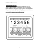
IDS 430/433 Users Manual Version 1.0 General Description This section gives you a general description on the operation of the IDS 430/433' s keyboard and display. The keyboard is used to initiate weighing functions, for data entry, maintenance, setup, and testing. The numeric display is used for weight and error display and for data entry. The LED status lights indicate the status of the weigh scale. Additional information about the keyboard and display is provided in section: Using the IDS 430/433.
IDS 430/433 Users Manual Version 1.0 The IDS 430/433 Display The IDS 430/433 DISPLAY consists of a 6 character NUMERIC display and 6 statuses LED’s The NUMERIC display is normally used to display the weight on the scale. The LED’s display the scale status. When lighted they indicate the following conditions: GROSS- The number displayed is the gross weight on the scale. NET - The number displayed is the net weight on the scale. MOTION- The weight on the scale is changing (not stable).
IDS 430/433 Users Manual Version 1.0 Installation and Setup This section provides information about unpacking, installing, and setup of the IDS 433/430. It also directs the installer to the appropriate sections of the manual for hardware and setup installation. Unpacking the IDS 433/430 Installation begins with unpacking the IDS 433/430. Observe any instructions or cautions, which appear in the shipping container.
IDS 430/433 Users Manual Version 1.0 Connect IDS 433/430 to host device (optional) The Serial Communications Port 2 (TB3) provides a continuous output of scale data. This is used for connection to a host device such as a computer or to a remote display (scoreboard). Continuous output transmission can be enabled or disabled and the output format can be customized to interface with the host device. See Hardware and Wiring Diagrams for pin assignments and sample cable drawings.
IDS 430/433 Users Manual Version 1.0 Setup Guide Initialize to Factory Defaults Setup the IDS 433/430 in the following order: The IDS 433/430 is initialized at the factory. The IDS 433/430 should be initialized when first powered up to guarantee no corruption occurred during shipping. It must be re-initialized if the program memory (EPROM) or the parameter memory (EAROM) is replaced. The Initialize function clears the memory and sets the configuration parameters to their default values.
IDS 430/433 Users Manual Version 1.0 NTEP LABELING INSTRUCTIONS Labeling Guidelines For NTEP Applications These guidelines pertain to the use of the IDS 433/430 in NTEP (National Type Evaluation Program) applications. If you are unfamiliar with NTEP, it is probable that this information can be disregarded for your application. NTEP has implications for “Legal-For-Trade” requirements only.
IDS 430/433 Users Manual Version 1.0 Using the IDS 430/433 The IDS 430/433 has 7 programmable function keys on the keyboard, a numeric keypad and 2 control keys (ENTER and CLEAR). This section of the IDS 430/433 manual describes what the keys are used for and how to use them. Keyboard Layout Operation of Function Keys The programmable function keys are located on the IDS 430/433’s front panel, including the F1 and F2 keys.
IDS 430/433 Users Manual Version 1.0 stores it in the tare register. The IDS 430/433 switches to NET mode and displays the net weight. KEYBOARD TARE: Use the numeric keys to enter a tare weight. Press the TARE key. The IDS 430/433 stores the entered weight in the tare register and switches to NET mode and displays the net weight. CLEAR TARE: Press the numeric ZERO key. Press the TARE key. The tare weight is cleared to zero and the IDS 430/433 switches to the GROSS mode displaying the gross weight.
IDS 430/433 Users Manual Version 1.0 Built In Application Programs The following built in programs are available to enable: 1. Fill to Setpoint. 2. Checkweigh: Under/Between/Over. 3. Weigh-in / Weigh-out. 4. Axle Weigh/Container weighing – Short Scale. 5. Axle Weigh – Long Scale. 6. ID Tare and Total. 7. Peak Hold. Use parameter function 73, “Initialize Function Memory”, to activate a built in program. See section 7 (page 7-8) for more details.
IDS 430/433 Users Manual Version 1.0 # 1 Fill to Setpoint Press the F1 key, the display prompts “SEt Pt” key in the setpoint value and depress the Enter key. Place an empty container on the scale. Press the F2 key to begin filling. TTL output 1 turns on until the weight on the scale is equal or greater than the setpoint. Connect TTL out put 1 to a relay to turn on motors, open and close gates, turn on and off flow valves for automated filling or indication.
IDS 430/433 Users Manual Version 1.0 # 2 Checkweigh: Under/Between/Over The indicator monitors the scale for activity, when the scale goes above the ‘empty’ weight, the indicator waits for a stable weight, and then outputs an indication of Under, Between (OK), or over. The cycle resets when the scale goes below the empty weight. Installation Connect TTL outputs to relays or lamp actuators.
IDS 430/433 Users Manual Version 1.0 # 3 Weigh-in / Weigh-out This program uses the ID memory for weigh-in / weigh-out transactions. An ID record is created using the Weigh-in function. The Weigh-out function recalls the ID, calculates Gross/Tare/Net of the transaction, prints the transaction, and adds the net weight to the ID’s totals register. The ID data is saved for further weighin/weigh-out transactions, or weigh-out only transactions.
IDS 430/433 Users Manual Version 1.0 REBUILD ID MEMORY: Press the ENTER key when the display prompts, “rebuiLd”. The display then prompts “id”. Enter the numeric 0 then press ENTER to rebuild ID memory. COUNT UNUSED ID’S: Press the ENTER key when the display prompts “Count”. The display prompts “FrExxx” where xxx is the number of unused ID records in memory. Set Beginning Sequence Number Depress the number 9 key and then the ENTER key.
IDS 430/433 Users Manual Version 1.0 # 4 Axle Weigh – Short Scale Automatically weigh multiple axles (or containers), print each axle weight, and print axle (or containers) total. Installation Connect the Red light / Green light relays. Green light = TTL out 1 TB4 Pin 1 Red light = TTL out 2 TB4 Pin 2 Ground = GND TB4 - Pin 4 + 5 volts DC +5v TB3 - Pin 1 Setup Parameters Configure the following parameters: Parameter 43 Trip level weight. Determines when an axle is on the scale.
IDS 430/433 Users Manual Version 1.0 # 5 Axle Weigh – Long Scale, Unattended Automatically weigh multiple axles (or containers), print each axle weight, and print axle (or containers) total. Installation Connect the Red light / Green light relays. Green light = TTL out 1 TB4 pin 1 Red light = TTL out 2 TB4 pin 2 Ground = GND TB4 - Pin 4 + 5 volts DC +5v TB3 - Pin 1 Setup Parameters Configure the following parameters: Parameter 43 Trip level weight. Determines when an axle is on the scale.
IDS 430/433 Users Manual Version 1.0 # 6 ID, Tare, and Total This program uses the ID memory to store tare weights and totals. Enter ID and Tare Data Press the F1 key. The display prompts "id". Enter up to 8 digits for ID and then press the ENTER key. The display prompts “tArE”. Enter the tare weight for that ID. Recall ID and Tare Press the F2 key. The display prompts "id". Enter up to 8 digits for the weigh-out ID and then press the ENTER key.
IDS 430/433 Users Manual Version 1.0 Set Beginning Sequence Number Use the numeric keypad to enter number 1. The display prompts "reg 1" for 1 second and then displays the current value. Press the CLEAR key if no change is to be made, or enter a new value and then press the ENTER key. The next sequence number printed will be the entered value +1. Notes • The ID file maintenance functions are password level 1 protected.
IDS 430/433 Users Manual Version 1.0 # 7 Peak Hold Function The peak hold register maintains the peak weight detected by the weight indicator. Enable Peak Hold Access configuration parameter 75. Enter a 1 to enable peak hold, enter a 0 to disable peak hold. Clear Peak Hold Register Press the CLEAR key to reset the peak hold register to 0. Use the Scale Basic built in function Clear Peak [143] to reset the peak hold register.
IDS 430/433 Users Manual Version 1.0 Set Operation Parameters This section describes the operation parameters of the IDS 430/433 and how their settings affect the operation of the weight indicator. Access Operation Parameters and Parameter Functions The parameters are accessed by holding the CLEAR key down and then pressing the ENTER key. The numeric display will prompt “CFG xx” where xx is the currently selected parameter. Enter the parameter number to be modified and then press the ENTER key.
IDS 430/433 Users Manual Version 1.
IDS 430/433 Users Manual Version 1.
IDS 430/433 Users Manual Version 1.0 Parameter Functions Fn. No 59 60 61 62 63 64 65 66 67 68 69 70 71 72 73 74 75 76 78 79 80 81 82 83 Function Name Display Calibration Audit Number Calibrate Scale - Deadload first Calibrate Scale - span first Calibrate Deadload Only Adjust Gain Calibration Configure Passwords Configure Print Formats Set Time and Date Display Operation Parameters Print Operation Parameters Diagnostic Tests Initialize Operation Parameters to factory defaults.
IDS 430/433 Users Manual Version 1.0 Scale Parameters The scale parameters configure IDS 430/433 for the weigh platform or load cell that it is connected to. The preceding table titled “SCALE PARAMETERS” lists the scale parameters and their factory settings. Use the “Field Setting” column to record any changes made to the factory default values. Many of the following parameters are entered in terms of “graduations”.
IDS 430/433 Users Manual Version 1.0 Parameter 4. Motion Detection Delay (6) Motion detection delay is used by the motion detection function to determine if the scale is in motion (not stable). Enter the amount of time (in tenths of a second) that the scale must be stable for motion status to be false (scale status = stable). Example: 0 = disables motion detection. 2 = 0.2 second delay before motion = false (stable = true). 15 = 1.5 second delay. 30 = 3.0 second delay. Parameter 5.
IDS 430/433 Users Manual Version 1.0 Parameter 9. Push Button Zero Percent (100) Enter the percent of full-scale capacity that can be acquired as the zero point with the ZERO key. 1 = 1%, 2 = 2%, ... 100 = 100%. Parameter 10. Primary Units Type (1 [lb]) The scale is calibrated in the primary units. The UNITS key is used to toggle the weight display between primary units and alternate units.
IDS 430/433 Users Manual Version 1.0 Parameter 14. Alternate Decimal Point (1) Enter the decimal point position for the alternate units display. Parameter 15. Alternate Count-by (5) Enter the alternate units count-by. Parameter 16. Alt Units Conversion Factor (45,360) The IDS 430/433 calculates the alternate weight by multiplying the primary weight by the conversion factor and then dividing by 100,000. The following table lists some common conversions.
IDS 430/433 Users Manual Version 1.0 Parameter 20. Disable Power-On Zero (1 [disabled]) Enter a 1 to disable the power-on zero function. Enter a 0 to enable power-on zero. The power-on zero function attempts to acquire zero when the power on tests have completed. If the weight on the scale is above the zero range the display prompts “Err 0”. Press the ENTER key to view the scale weight. Remove the weight from the scale to enter weighing mode. Parameter 21.
IDS 430/433 Users Manual Version 1.0 Parameter 24 Serial Port 1 Baud Rate (1 [9600 baud]) Enter a baud number from the table below to select a baud rate from the description column. (*HS baud rates for the 100 samples per sec version only). Baud Number Baud Description 1 2 3 4 5 6 9600 Baud 4800 Baud 2400 Baud 1200 Baud 600 Baud 300 Baud (* HS 19.2K) 7 150 Baud (*HS 38.
IDS 430/433 Users Manual Version 1.0 Parameter 27 TX2 Control / Station ID (255 [single station]) Serial Port 2 can be used for continuous transmission of scale data or as a network buss or for single station remote control. Enter a 0 to enable continuous transmission of TX 2 data. The data sent is configured in parameter 28 (TX2 Format).
IDS 430/433 Users Manual Version 1.0 Printer Parameters The IDS 430/433 provides a universal printer interface for various printers. The printer interface allows you to select and customize the data output for serial or parallel printers. The serial interface option uses Serial Port 1 (TB1) for connection to the printer. The parallel interface uses the TTL I/O Port (TB4) for connection to the printer. Refer to the “HARDWARE INSTALLATION AND WIRING “ section for information on connector pin designations.
IDS 430/433 Users Manual Version 1.0 Parameters 35, 36, 37, and 38: Print Codes The IDS 430/433 provides 4 programmable print codes. The print codes are used to send special setup parameters to the printer, such as select print size or select print font. Each print code is up to 4 characters long. Consult your printer manual for the print codes that you may want to use. Enter the codes in decimal format (an ASCII carriage return = 13). Select parameter 35 to begin print code 1 entry.
IDS 430/433 Users Manual Version 1.0 Display Intensity, Battery, Watch Dog Timer Parameter 40 Display Intensity (10) Use parameter 40 to set the brightness of the IDS 430/433’s numeric display and LED indicators. The brightness can be set from 1 (dimmest) to 15 (brightest). Parameter 41 Battery Backup (0 [no]) The battery is used to preserve the time and date, memory registers, and ID memory when power is lost.
IDS 430/433 Users Manual Version 1.0 Parameter Functions The parameter functions are used to set parameters that are too complex for a single numeric entry. The following table lists the parameter functions: Parameter Functions Fn.
IDS 430/433 Users Manual Version 1.0 To exit configuration and store changes, press the CLEAR key when “CFG xx” is being displayed. To exit configuration and NOT store changes, enter 999 when “CFG xx” is being displayed. The display prompts “Abort”. Press the ENTER key to abort (exit without saving changes) or press the CLEAR key if you do not want to abort. Example: Begin Calibration of the Scale- The IDS 430/433 is in the display weight mode.
IDS 430/433 Users Manual Version 1.0 Function 60 Calibrate Scale - Deadload First Use function 60 to calibrate the scale by reading the deadload first and then reading the span. Set the Scale Operation Parameters before using function 60. Best results are obtained when the IDS 430/433 and load cells have reached thermal equilibrium (power applied for approximately 30 to 120 minutes depending on load cell size). NOTE: function 60 automatically adjusts parameter 19 (deadload offset).
IDS 430/433 Users Manual Version 1.0 Function 62 Calibrate Deadload Only Use function 62 to re-calibrate the deadload weight without affecting the span calibration. 1. Hold the CLEAR key down and press the ENTER key to enter the configure mode. 2. Enter CFG 62. The IDS 430/433 prompts “dEAdld”. Remove all weight from the scale. Press the ENTER key. The IDS 430/433 reads the scale’s deadload weight. 3. The IDS 430/433 prompts “CFG 62”. Press the CLEAR key to exit the configure mode.
IDS 430/433 Users Manual Version 1.0 Function 64 Configure Passwords Use function 64 to enter password data. The IDS 430/433 provides three security passwords that can be activated and entered to protect configuration data. Password 1 is used to protect I/O port configuration, setpoint, and event monitor data. Password 2 is used to protect calibration and scale configuration data. Security level 3 provides extra protection for password level 2 data.
IDS 430/433 Users Manual Version 1.0 Function 65 Configure Print Formats Use function 65 to modify print formats to meet your print requirements. The print formats are grouped into PAGES that are used for generating print data onto a form. Each page is organized into rows and columns as follows: Line No. Column No. Item No. Line No. = Line number on the page to print the item on. Column No. = Column position where item print begins. Item No. = Item to print.
IDS 430/433 Users Manual Version 1.0 6. The IDS 430/433 prompts “i x” where x is the item number that is to be printed. (See Print Item List for a description of items that can be printed). Enter a new item number or press the ENTER key to use the displayed number. 7. The IDS 430/433 prompts “Px E2”. Use the procedure above to modify entry 2. Use the UNITS key (↓) to scroll forward in the page table, use the PRINT key (↑) to scroll backwards. 6. 8.
IDS 430/433 Users Manual Version 1.0 Page List FORMAT PAGE 1 PAGE 2 PAGE 3 PAGE 4 DESCRIPTION Prints when the IDS 430/433 is in the GROSS weight mode. Prints when the IDS 430/433 is in the NET weight mode. Used by Scale Basic functions when needed. Used by Scale Basic functions when needed. Print Item List Item # Description 2-4 84-90 5 6 7 8 9 10 11 12 15 16 17 18 21 22 23 24 25 26 27 32 33 34 35 40 41 42-46 51-66 84-90 Print Label 1, 2, and 3 (see chap.
IDS 430/433 Users Manual Version 1.0 Print Format Design Example EXAMPLE PRINT: 1111111111222222222233333333334 COLUMN 1234567890123456789012345678901234567890 LINE 1 2 3 4 5 6 7 GROSS 54785 LB TARE 12451 LB NET 42243 LB TIME 03:45 PM DATE 05 AUG 1999 EXAMPLE FORMAT DESIGN WORKSHEET: Page:1 Item Description E1 E2 E3 E4 E5 Line No. Column Item No. 3 4 5 7 0 4 4 4 1 0 5 6 7 10 0 Gross Weight Tare Weight Net Weight Time and Date End of Print NOTE: A zero in the Line No column terminates printing.
IDS 430/433 Users Manual Version 1.0 Format Design Worksheets Page E1 E2 E3 E4 E5 E6 E7 E8 E9 E10 E11 E12 E13 E14 E15 E16 Item Description Page Item Description Line No. Line No. E1 E2 E3 E4 E5 E6 E7 E8 E9 E10 E11 E12 E13 E14 E15 E16 - 50 - Column Column Item No. Item No.
IDS 430/433 Users Manual Version 1.0 Function 66 Set Time and Date Use function 66 to set the time and date. Entering 19 can display the time and date when the meter is in the idle mode. Date will be printed in a Y2K compliant four-digit year. 1. Hold the CLEAR key down and press the ENTER key to enter the configure mode. 2. Enter CFG 66. The IDS 430/433 prompts “t”. Enter the time using 5 digits. The last digit should be 0 for AM, 1 for PM, or 2 for 24-hour time. 3. The IDS 430/433 prompts “D”.
IDS 430/433 Users Manual Version 1.0 Function 69 Diagnostic Tests 1. Hold the CLEAR key down and press the ENTER key to enter the configure mode. 2. Enter CFG 69. The IDS 430/433 prompts “diA xx” where xx is the currently selected test number. Enter a test number or press the ENTER key to use the displayed number. 3. The IDS 430/433 begins the selected test. Press the CLEAR key when the test is complete. Test # 1 2 3 4 5 6 7 8 9 10 11 12 13 Hardware Tested Description Serial Com. Port 1 Serial Com.
IDS 430/433 Users Manual Version 1.0 Function 71 Configure Event Monitor Use function 71 to enter setpoint data into the Event Monitor. See the “Scale Basic / Event Monitor” manual” for more information on the event monitor parameters. 1. Hold the CLEAR key down and press the ENTER key to enter the configure mode. 2. Enter CFG 71. The IDS 430/433 prompts “Eno”. Enter the Event number to be modified. 3. The IDS 430/433 prompts “P0 xx” where P0 is parameter 0 and xx is the current value of parameter 0.
IDS 430/433 Users Manual Version 1.0 Function 73 Initialize Function Memory The initialize function erases function memory and setpoint monitor memory, and initializes all parameters with password level 1 or 2. Function 73 prompts “rs Fn” . Press the Enter key to initialize only or enter a number below to activate a built in program. 1. Fill to Setpoint. 2. Checkweigh: Over/Between/Under 3. Weigh-in / Weigh-out 4. Axle Weigh – Short Scale 5. Axle Weigh – Long Scale 6. ID Tare and Total 7.
IDS 430/433 Users Manual Version 1.0 Function 74 Configure Timers The display prompts “tr” when function 74 is activated. Enter the timer number to be modified (1 to 5) then press the ENTER key. The first parameter (L) is the time length in tenths of a second. The second parameter (Fn) is the function number to be executed when the timer times out. Parameter 75 Enable Peak Detect Enter a 1 to enable peak detect, enter a 0 to disable peak detect.
IDS 430/433 Users Manual Version 1.0 Function 80 Calibrate - Multi-point Linearization Use function 80 to calibrate the scale using up to 5 calibration points to ' linearize' the load cell. Set the Scale Operation Parameters before using function 80. Best results are obtained when the IDS 430/433 and load cells have reached thermal equilibrium (power applied for approximately 30 to 120 minutes depending on load cell size). NOTE: function 80 automatically adjusts parameter 19 (deadload offset). 1.
IDS 430/433 Users Manual Version 1.0 Diagnostic Tests The DIAGNOSTIC TESTS are accessed using configuration function 69. Hold the CLEAR key down and press the ENTER key. The display prompts “CFG xx” where xx is the currently selected parameter. Enter 69 and press the ENTER key to access the DIAGNOSTIC TESTS. The display prompts “diA xx” where xx is the last selected diagnostic function. Select a test number from the table below. Enter the test number and press the ENTER key.
IDS 430/433 Users Manual Version 1.0 Diagnostic Test 2: Serial Com Port 1 – Display Errors This test displays the number of framing and parity errors that are detected in the input data stream. The error count is set to zero when entering this test. New errors are displayed as “PxxFxx” where Pxx is the number of parity errors and Fxx is the number of framing errors. If the error count exceeds 99, the display will remain at 99. Press the CLEAR key to exit Diagnostic test 2.
IDS 430/433 Users Manual Version 1.0 Diagnostic Test 7: Test parallel output This test transmits data out the parallel TTL I/O port. The display prompts: “dAtA”. Use the numeric keyboard to enter data. Press the ENTER key to transmit the data. If the data is successfully sent, “ 1= xxx” is displayed, where xxx is the first 3 characters of the data sent and 1= is the number of times that the data has been sent. Press the ENTER key to send the data again. Press the CLEAR key for the “dAtA” prompt.
IDS 430/433 Users Manual Version 1.0 Diagnostic Test 11: Print the EAROM Configuration Table This function sends the contents to the EAROM configuration memory to the printer. Use this function to document your setup of the when installation is complete. Diagnostic Tests 12 & 13: Loop Back Tests These tests are used by the factory to test the serial ports transmit and receive functions.
IDS 430/433 Users Manual Version 1.0 Troubleshooting The following table describes the probable causes to some problems you may encounter. Most problems can be resolved by using the information provided in the table. Printer does not print (serial RS232) * Cable connection problem or invalid pin connections. * Baud rate and format on serial port 1 does not match printer. * Transmitter/receiver IC damaged (U3 MC145406).
IDS 430/433 Users Manual Version 1.0 Error Messages Error Err 0 Err 1 Err 2 Err 3 Err 4 Err 5 Err 5.1 Err 6 Err 7 Err 8 Err 9 Err 10 Err 11 Err 12 Err 14 Err 15 Err 16 Err 18 Err 21 Err 22 Err 23 Error OL undEr Description Power on zero error. See parameter 20. Keyboard error. Occurs during power up while a key on the keyboard is being pressed or one of the remote switch inputs is activated. Restart Trap. The microprocessor accessed nonexistent memory location.
IDS 430/433 Users Manual Version 1.0 HARDWARE INSTALLATION AND WIRING This section describes installation and wiring information for the interface ports. There are two bi-directional serial ports, digital port with 3 TTL inputs, 3 TTL outputs, and one load cell input port. The serial ports are used to interface to a printer and to a host device or PC for continuous output. The TTL outputs and inputs are used for remote switch input and relay control.
IDS 430/433 Users Manual Version 1.0 11 12 13 14 15 16 1 2 3 4 TXD 2 (RS232) (CL2 TX -) RXD 2 (RS232) RS485 TX RS485 TX + RS485 RX RS485 RX + Digital Output Port Connector TB4 TTL OUT 1 TTL OUT 2 TTL OUT 3 GROUND P.C.
IDS 430/433 Users Manual Version 1.0 ISOLATED ANALOG OUTPUT OPTION IDS 430/433-AO ANALOG OUTPUT OPTION The Analog Output option board is internally mounted inside the IDS indicator. The Analog Output has two jumpers, JP1 & JP2. These jumpers are used to configure the output format. Terminal block TB1 is for making external wiring connections. JP1 & JP2 are factory set for 4-20mA. Refer to the diagram below for configuration, format and alternative wiring.
IDS 430/433 Users Manual Version 1.0 ASCII CHART ASCII Null SOH STX ETX EOT ENQ ACK Bell BS HT LF VT FF CR SO SI DLE XON TAPE XOFF DC4 NAK SYN ETB CAN EM SUB ESC FS GS RS US DEC 00 01 02 03 04 05 06 07 08 09 10 11 12 13 14 15 16 17 18 19 20 21 22 23 24 25 26 27 28 29 30 31 ASCII SP ! " # $ % & ' ( ) * + , .
IDS 430/433 Users Manual Version 1.