IDS 550 DATA TERMINAL TECHNICAL MANUAL 9/90
TABLE OF CONTENTS 1. Installation * Unpacking instructions * Get the IDS 550 ready for data input and printing 2. How to change the IDS550 configuration * * * * How How How How to to to to begin the configuration program use the Keyboard when configuring Configure the Standard Parameters Configure Application Parameters 3. Page Printer Configuration Guide 4. IDS550 Troubleshooting Guide * How to diagnose the problem using IDS 550 test functions * Problem resolution 5.
mechanism. Install the printer ribbon as shown on the diagram affixed to the dot head cover. * Get the IDS 550 ready for data input and printing ----------------------------------------------------------------1. Be sure the print-mechanism shipping restraint has been removed. 2. Connect the IDS550 to the weigh meter via the 25 pin 'D' connector at the back of the printer. See Appendix I for communication port wiring information. 4. Connect the IDS550 to AC power. 5. Turn power on.
ENTER - Enter data and go to the next step. CLEAR - EXIT The configuration functions use "scrolling menus". A scrolling menu is a list of options that are viewed by pressing the CONTINUE key or the REVIEW key. The CONTINUE key advances the display to the next item in the menu, the REVIEW key retreats to the previous item. The ENTER key selects the item being displayed. The CLEAR key is used to exit from a menu. EXAMPLE: Press the Square Configure switch.
STANDARD PARAMETERS WORKSHEET --------------------------------------MENU SELECTION | PARAMETER | DEFAULT | FIELD SETTING ===================================================================== 1 INITIALIZE SYS | none (resets all parameters to factory settings) --------------------------------------------------------------------2 SELF TEST | TEST SCALE PORT| | --------------------------------------------------------------------| TEST SERIAL OUT| | |--------------------------------------------------| UNUSED ID'
1 INITIALIZE SYSTEM ------------------------------------------------------------------This function ERASES memory and RESETS all the parameters to their default setting!!! When INITIALZIE SYSTEM is activated the IDS550 prompts: "ENTER=INITIALIZE". Press the ENTER switch to initialize the system or press the CONTINUE (or CLEAR) key to exit WITHOUT initialization.
"BAUD "BAUD "BAUD "BAUD = = = = 1200"2400"4800"9600"- selects selects selects selects 1200 2400 4800 9600 baud. baud. baud. baud. Press the CONTINUE key to scan the baud rate selections. Press the ENTER key to complete the baud rate selection. The IDS550 prompts: "N DATA N STOP" where N DATA = number of data bits per character, N STOP = number of stop bits per character.
5 CONFIGURE SCALE ------------------------------------------------------------------The IDS550 prompts: "CONDEC/WS700T" (or current meter that is selected.) The meter select menu is: "NCI5790" "ANALOGIC AN5316" "CONDEC / WS700T" "AND / GENERAL" "CARDINAL 738" "TOLEDO 8142" "WI 110" "DR 10K" "SSD800" "HR 50 LIBERATOR" "FB90-165" Press the CONTINUE key to scan the meter list. key to select a meter type.
If the IDS550 internal motion detect option is installed The IDS550 prompts: "MOTION TIME XX" where XX is the time between motion detect samples (tenths of seconds). Press ENTER to use the displayed time or enter a new motion detect interval time. The IDS550 prompts: "MOTION RANGE XX" where XX is allowable weight deviation for the scale = not in motion. Press ENTER to use the displayed range or enter a new motion detect range.
The above steps are repeated for password 2 . !!!!!!!!!!!!!!!!!!!!!!!!!!!!!!!!!!!!!!!!!!!!!!!!!!!!!!!!!!!!!!! !!! WARNING: ONCE A PASSWORD IS ENTERED IT MUST BE MEMORIZED. IF YOU FORGET THE PASSWORD THERE IS NO WAY TO ACCESS THE PROTECTED FUNCTIONS. !!!!!!!!!!!!!!!!!!!!!!!!!!!!!!!!!!!!!!!!!!!!!!!!!!!!!!!!!!!!!!! The PASSWORD function inserts an additional step when accessing protected functions: The IDS550 prompts: "ENTER PASSWORD". The correct password must be entered before continuing.
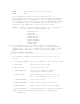
--------------------------------------------------------------------3 PAGE PRINTER CONFIGURATION GUIDE ------------------------------------------------------------------Activate the CONFIGURE menu and press the ENTER key when the IDS550 displays 'CONFIG PAGE'. The IDS550 prompts: "HEADER LABEL" Enter up to 16 characters for the header label or press CONTINUE to skip header label entry. The HEADER LABEL is printed when item #2 is selected in the page-printer item list.
follows the PAGE WORKSHEET. 2. Activate page configuration. 3. Enter the data from the PAGE WORKSHEET into the IDS550. 4. Enter a 0 for the line_no after the last data item.
| 0 | 0 | 0 | 0 | -------------------------------------| | | | | -------------------------------------NOTE: A zero in line no. column terminates printing. Use zero only after all required information has been entered.
-------------------------------------------------------------------4. TROUBLESHOOTING GUIDE -------------------------------------------------------------------1. SCALE INPUT ERROR on Power Up. The IDS550 internal switch is set for Current Loop input and no idle current is detected. The signal wires may be reversed or connected to the wrong pins. The meter may not be sending. 2. NO DISPLAY, NO AUDIO ON POWER UP. Check power cable. Check the fuse on the back of the IDS550. 3. NO WEIGHT DISPLAY.
. . . 3 2 1 F3 F2 F1 Q3 Q2 Q1 CR5 CR4 CR3 CR15 CR14 CR13 --------------------------------------------------------------------5. Interface Port Connections --------------------------------------------------------------------The IDS550 has 3 interface ports: 1. SERIAL CHANNEL 1: RS232 or CURRENT LOOP The input of Channel 1 is normally used for interfacing to a weigh meter. 2. SERIAL CHANNEL 2: RS232, CURRENT LOOP, or RS485. Channel 2 is used for interfacing to a second weigh meter or a computer. 3.
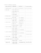
CURRENT LOOP OUTPUT: CL OUT - pin 24 CL OUT + pin 20 (usually used for printer output) SERIAL CHANNEL 2 WIRING LIST ( 25 PIN 'D' CONNECTOR ) ----------------------------------------------------------------SIGNAL PIN # #2 RS232 RXD #2 RS232 TXD 9 ---- Jumper W3 10 IN #2 CUR LOOP IN + #2 CUR LOOP IN #2 CUR LOOP OUT 18 ---- Jumper W5 19 24 IN #2 RS422/485 IN + #2 RS422/485 IN - 18 ---- Jumper W4 21 IN #2 RS422/485 OUT + #2 RS422/485 OUT - 11 12 +5R (soft 5V) GND 23 13 PARALLEL TTL WIREING LIST
----------------------------------------------------------------PIN SIGNAL 1 2 3 4 5 6 7 8 9 10 11 12 13 14 15 16 17 18 19 20 21 22 23 24 CHASSIS GND #1 RS232 TXD #1 RS232 RXD #1 RS232 RTS #1 RS232 CTS +5 R GND #1 CUR LOOP IN + #2 RS232 RXD #2 RS232 TXD #2 RS485 + #2 RS485 GND #1 PULSE INPUT TTL INPUT TTL INPUT #2 CUR LOOP IN + (#2 RS422 IN +) #2 CUR LOOP IN +8 R #2 RS422 IN #1 CUR LOOP IN +5 V #2 CUR LOOP OUT NOTES: Set the switch inside the IDS550 to the RS232 position for RS232 input (slide to left - t