Product Manual The Essential Guide for Safety Teams and Instrument Operators Edition: 10 April 15, 2019 Part Number: 17156830-1
Industrial Scientific Corporation, Pittsburgh, PA USA Industrial Scientific Co., Ltd. Shanghai, China © 2015, 2016, 2017, 2018, 2019 Industrial Scientific Corporation All rights reserved. Published 2019. Revision 9 www.indsci.
Contents General Information ...................................................................................................................................... 7 Certifications ................................................................................................................................................................................. 7 Warnings and Cautionary Statements ....................................................................................................................
Power Off .................................................................................................................................................................................... 52 Settings ....................................................................................................................................................... 53 Guidelines ...............................................................................................................................................
Maintenance ................................................................................................................................................ 99 Guidelines ................................................................................................................................................................................... 99 Process At-a-glance...........................................................................................................................................
Tables and Figures Table 1.1 Hazardous-area certifications ........................................................................................................................................... 7 Table 1.2 Wireless certifications ....................................................................................................................................................... 8 Table 1.3 Warnings and cautionary statements...............................................................................
Figure 5.5 LENS group peer-instrument locations .......................................................................................................................... 82 Figure 5.6 Join a LENS group......................................................................................................................................................... 83 Figure 5.7 Leave a LENS group ...........................................................................................................................
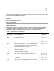
1 General Information Certifications Warnings and Cautionary Statements Recommended Practices Certifications Certifications for the Ventis® Pro4 Multi-Gas Monitor and Ventis® Pro5 Multi-Gas Monitor, at the time of this document's publication, are listed below in Tables 1.1 and 1.2. To determine the hazardous-area classifications for which an instrument is certified, refer to its label or the instrument order. Table 1.
Table 1.
Table 1.2 Wireless certifications Agency or authority Identification number or registration number Country or region IC 216Q-1740, 7084A-SM200, 20727-VPX Canada NCC CCAJ18LP0C30T2 and CCAJ18LP0C31T2 Taiwan NTC sn 549 and sn 550 Thailand TRCa TRC/LPD/2018/159 Jordan aVentis Pro 5 only Warnings and Cautionary Statements Read and understand this Product Manual before operating or servicing the instrument.
Table 1.3 Warnings and cautionary statements °C (32 °F), the stabilization time is approximately 15 minutes; with smaller or larger changes in temperature, stabilization time will be shorter or longer, respectively. Note: If the sensor is to be zeroed after a sudden change in ambient-air temperature, allow the sensor and its readings to stabilize before zeroing. The Long-life O2 sensor (part number 17155304-Y) is a biased sensor, requiring continuous power to operate to specification.
Table 1.3 Warnings and cautionary statements Battery contacts are exposed on batteries when they are removed from the instrument. Do not touch the battery contacts and do not stack batteries on top of each other. Do not use solvents or cleaning solutions on the instrument or its components.
Table 1.3 Warnings and cautionary statements The batteries are not user-replaceable. The aspirated version of the Ventis Pro 4 and Pro 5 is approved for use with the P/N 17148313-2 extended battery only. To be charged on the surface or underground in accordance with 30 CFR 75.340 (the applicable regulations pertaining to battery-charging stations) and MSHA Program Information Bulletin PIB P11-12. Charge monitors with an Industrial Scientific Corporation charger designed for use with this monitor.
Bump Test (or "functional test") Bump testing is a functional test in which an instrument's installed sensors are to be briefly exposed to (or “bumped” by) calibration gases in concentrations that are greater than the sensors’ low-alarm setpoints. This will cause the instrument to go into low alarm and will indicate which sensors pass or fail this basic test for response to gas. Zero Zeroing adjusts the sensors’ “baseline” readings, which become the points of comparison for subsequent gas readings.
Note: The use of calibration gases not provided by Industrial Scientific may void product warranties and limit potential liability claims. First use To prepare the Ventis Pro Series instrument for first use, qualified personnel should ensure the following are completed: • Charge the battery. • Review instrument settings and adjust them as needed. • Calibrate the instrument. • Complete a bump test. Wearing the instrument Based on the U.S.
Table 1.5 Minimum sample time for common sample-line lengths Sample-line length Base time (minutes) + Sample-line-length factor = Minimum sample time (mm:ss) 3.05 m (10 ') 2 min + (10 ' x 2 s) = 02:20 6.10 m (20 ') 2 min + (20 ' x 2 s) = 02:40 9.14 m (30 ') 2 min + (30 ' x 2 s) = 03:00 12.10 m (40 ') 2 min + (40 ' x 2 s) = 03:20 15.24 m (50 ') 2 min + (50 ' x 2 s) = 03:40 18.29 m (60 ') 2 min + (60 ' x 2 s) = 04:00 21.
Note: The intended wireless performance is supported through docking station operations, which provide regular instrument and wi-fi battery firmware updates along with maintenance tasks. *Available when the iNet Now service has been activated and all instruments to be monitored have been activated for live monitoring. Table 1.
2 Product Information Instrument Overview System Overview Key Features Compatibility Specifications Instrument Overview The Ventis® Pro Series portable gas monitors are used for personal protection to monitor for oxygen and a variety of toxic gases and combustible gases. Thirteen compatible sensors are available for use with the Ventis Pro4 Multi-Gas Monitor, which can provide readings for up to four gases.
• • Provide its user with a panic alarm. Self-activate a man-down alarm when it senses it is no longer being operated by its user. When part of a LENS Wireless group, the Ventis Pro can operate as a “peer” equipment item. Peer instruments share with one another their gas readings and alarms, allowing workers to learn of nearby hazardous conditions and the user names of colleagues who may be in distress.
RGX Gateway iNet Instrument data RGX Gateway iNet Now users (live monitoring and subscription-based alerts) Ventis Pro Wi-fi Battery Instrument data Figure 2.1 Industrial Scientific live-monitoring system Key Features LENS Wireless Ventis Pro instruments are equipped with LENS Wireless, a long-range, power-efficient wireless mesh network from Industrial Scientific, which enables the wireless connection of gas-detection instruments and other equipment items to form a LENS group.
With a setting of on, the wi-fi battery is operational—it is not turned on or off by the worker. However, the instrument can be set to allow its user to update the battery’s network credentials, during startup or during operation, using an iAssign tag that is programmed with the proper credentials. When a wi-fi battery is installed, but its setting is turned off, the following apply. • The battery will power the instrument.
The man-down feature allows the instrument to sense when it has not moved. A man-down warning or alarm may indicate the instrument operator is unable to move or press the panic button, or that the instrument has become separated from its operator. Both the warning and alarm can be turned off by the user. An instrument’s man-down functionality can be temporarily disabled when the instrument’s site name is updated by an iAssign Beacon that is broadcasting a special site name.
Gas-information access Optional gas-information displays are used to provide the instrument operator with the setpoints for gas events and calibration gas concentrations. The information can be set to display during the start-up sequence, be accessible during operation, or both. DualSenseTechnology DualSense® Technology enables the use of redundant sensors, two installed sensors of the same type that are DualSense capable.
Compatibility Sensors Each instrument’s compatible sensors can be installed in one or more specific locations as depicted in Figures 2.2.A and 2.2.B for Ventis Pro4 and Ventis Pro5, respectively. Table 2.1 provides the same information but in list format, which is helpful for distinguishing among sensors of the same type. For example, there are two H2S sensors that do not share installation locations or part numbers.
Locations 1 or 2 Carbon Dioxide (CO2); 17155304-Q Carbon Monoxide/Hydrogen Sulfide (CO/H2S); 17155304-J Hydrogen Sulfide (H2S); 17155304-2 Oxygen (O2); 17155304-3* Oxygen, Long-life (O2); 17155304-Y* Location 2 only Carbon Dioxide/LEL (Propane), IR (CO2/LEL); 17155304-U Carbon Dioxide/Methane (CO2/CH4); 17155304-V LEL (Pentane); 17155304-K LEL (Methane); 17155304-L Methane, 0-5% vol; 17155304-M Methane IR, (CH4); 17155304-N Locations 3 or 4 Ammonia (NH3); 17155306-6 Carbon Monoxide (CO); 17155306-1* Carbo
Table 2.
DO NOT USE THE WI-FI ENABLED BATTERY PACK WITHIN CLOSE LOCATION TO BLAST DETONATOR CIRCUITS. The Wi-fi enabled battery has not been assessed for usage near blasting circuits. Gateways Ventis Pro Series instruments are compatible with the RGX™ Gateway and smart-device gateway app from Industrial Scientific. Each gateway serves to exchange data between the enabled instruments and iNet─this supports live monitoring of the equipment items through iNet Now.
• When an access level is entered for the user, it can be read by the iAssign Beacon. An instrument proximity alarm will occur if the access level of its current user-name assignment is less than that of an in-range Beacon. • iAssign tags can also be programmed to contain data to update the network credentials for an installed wi-fi battery. Table 2.4.
Table 2.5 Instrument and pump specifications Item Description Alarm signals Visual (two red and two blue lights); audible (95 dB at a distance of 10 cm [3.94 "], typicala); and vibration Dimensions 104 x 58 x 36 mm (4.09 x 2.28 x 1.42 ") Weight 200 g (7.05 oz.), typicalb Ingress protection IP68 at 1.5 m (4.9 ′) for one hour Pump With 0.3175 cm (0.125 ") inside diameter sample tubing, sustains a continuous sample draw for up to 30.48 m (100 ').
Sensor Specifications Table 2.7 provides specifications for each sensor, which include properties, installation locations, operating conditions, and performance data. Table 2.7 Sensor specifications Gas type (abbreviation) Part number Ammonia (NH3) Carbon Dioxide (CO2) 17155306-6 17155304-Q Toxic Toxic Electrochemical Infrared No No Ventis Pro4 None 1 or 2 Ventis Pro5 3 or 4 1 or 2 -20 to +40 °C (-4 to +104 °F) -20 to +50 °C (-4 to +122 °F) 15-95% 0-95% 0−500 ppm 0−5% vol 1 ppm 0.
Table 2.7 Sensor specifications Gas type (abbreviation) Part number Carbon Dioxide/LEL (Propane), IR (CO2/LEL) 17155304-Uc Properties Category Toxic/Combustible Technology Infrared DualSense capable No Installation location Ventis Pro4 None Ventis Pro5 2 Operating conditions Temperature rangea -20 to +50 °C (-4 to +122 °F) RH rangea 0-95% CO2 LEL Measurement range 0-5% vol 0-100% LEL Measurement resolution 0.01% vol 0.01% LEL Calibration gas and concentration 2.
Table 2.7 Sensor specifications Gas type (abbreviation) Part number Carbon Dioxide/Methane (CO2/CH4) 17155304-Vc and e Properties Category Toxic and Combustible Technology Infrared DualSense capable No Installation location Ventis Pro4 None Ventis Pro5 2 Operating conditions Temperature rangea RH -20 to +50 °C (-4 to +122 °F) rangea Performance 0-95% CO2 CH4 Sensitivity Measurement range 0−5% vol 0−5% vol 5.01-100% vol Measurement resolution 0.01% vol 0.01% vol 0.1% vol 2.
Table 2.
Table 2.7 Sensor specifications Gas type (abbreviation) Part number Carbon Monoxide with low Hydrogen cross-sensitivity (CO/H2 Low) Hydrogen Cyanide (HCN) 17155306-G 17155306-B Toxic Toxic Electrochemical Electrochemical No No Ventis Pro4 3 or 4 3 or 4 Ventis Pro5 3 or 4 3 or 4 -20 to +50 °C (-4 to +122 °F) -30 to +40 °C (-22 to +104 °F) 15-95% 15-95% 0−1000 ppm 0−30 ppm 1 ppm 0.
Table 2.7 Sensor specifications Gas type (abbreviation) Part number Hydrogen Sulfide (H2S) Hydrogen Sulfide (H2S) 17155304-2 17155306-2 Toxic Toxic Electrochemical Electrochemical No Yes Ventis Pro4 1 or 2 3 or 4 Ventis Pro5 1 or 2 3 or 4 -40 to +50 °C (-40 to +122°F) -40 to +50 °C (-40 to +122°F) 15-95% 15-95% 0−500 ppm 0−500 ppm 0.1 ppm 0.
Table 2.
Table 2.7 Sensor specifications Gas type (abbreviation) Part number Methane, IR (CH4) Methane, 0-5% vol 17155304-N 17155304-Mc Combustible Combustible Infrared Catalytic bead No No Ventis Pro4 None 2 Ventis Pro5 2 2 -20 to +50 °C (-4 to +122 °F) -20 to +55 °C (-4 to +131 °F) 0−95% 15-95% Properties Category Technology DualSense capable Installation location Operating conditions Temperature rangea RH rangea Performance Sensitivity Measurement range 0−5% vol 5.
Table 2.7 Sensor specifications Gas type (abbreviation) Part number Nitrogen Dioxide (NO2) Oxygen (O2) Oxygen, Long-life (O2) 17155306-4 17155304-3 17155304-Y Toxic Oxygen Oxygen Electrochemical Electrochemical Electrochemical No Yes Yes Ventis Pro4 3 or 4 1 or 2 1 or 2 Ventis Pro5 3 or 4 1 or 2 1 or 2 -20 to +50 °C (-4 to +122 °F) -20 to +55 °C (-4 to +131 °F) -20 to +50 °C (-4 to +122 °F) 15-95% 5-95% 15-90% 0-150 ppm 0-30% vol 0-30% vol 0.1 ppm 0.1% vol 0.
Table 2.7 Sensor specifications Gas type (abbreviation) Part number Phosphine (PH3) Sulfur Dioxide (SO2) 17155306-9 17155306-5 Toxic Toxic Electrochemical Electrochemical No Yes Ventis Pro4 3 or 4 3 or 4 Ventis Pro5 3 or 4 3 or 4 -20 to +50 °C (-4 to +122 °F) -20 to +50 °C (-4 to +122 °F) 15-90% 15-90% Measurement range 0-10 ppm 0-150 ppm Measurement resolution 0.01 ppm 0.
3 Getting Started Unpacking the Instrument Hardware Overview Display Overview Power On Power Off Unpacking the Instrument The items that are shipped with the instrument are listed below in Table 3.1. Each item should be accounted for during the unpacking process. If any item is missing or appears to have been damaged, contact Industrial Scientific (see back cover) or an authorized distributor of Industrial Scientific products. Table 3.
Hardware Overview The instrument's main hardware components are identified below in Figures 3.1.A and 3.1.B for the diffusion and aspirated instruments, respectively (Ventis Pro5 shown). Front Red lights Sensor ports Sensor ports Panic button Blue lights Display screen Speaker NFC Power button Enter button Back Case bottom screw (x2) Clip Battery screw (x4) Battery Charging contacts Infrared data (IrDA) window Figure 3.1.
Front Inlet Cap Pump door hinge Barrel (houses water barrier) Pump door screw Pump door Panic button Red lights Blue lights Display screen Speaker NFC Power button Enter button Infrared data (IrDA) window Back Pump case (lower portion houses battery) Pump case screw (x4) Figure 3.1.
Display Overview The instrument’s easy-to-read display screen has three main horizontal segments. From top to bottom, they are: • Status bar • Gas readings area • Navigation bar The instrument uses these areas to display symbols, numbers, abbreviations, and text in combinations that allow it to clearly communicate with its user: the instrument operator in the field or team members who are responsible for maintaining the instrument. See Figures 3.2.A through 3.2.
Status bar During operation, the display screen’s status bar communicates basic information to the instrument operator: instrument and battery status (shown), ambient-air temperature, and the time of day. When the instrument is in a LENS group, the number of equipment items is shown along with the group's signal quality. Cloud symbols are used to indicate the instrument's iNet connection status. Instrument status symbol The status bar checkmark indicates the instrument is operational.
The battery’s level of charge is between 34 and 66%. The battery’s level of charge is less than or equal to 33%. The battery’s level of charge is approaching a critically low level. 11:34a The time of day (12-hour format shown). 76 F The ambient-air temperature reading (Fahrenheit shown). Gas readings area In addition to the display of current gas readings, this area communicates status information about the installed sensors. Gas reading Gas, unit of measure, and current reading.
Status bar Gas readings area In the event of an instrument warning or alarm, the gas readings area communicates the event type, details about the alarm, and gas readings for all sensors. Peer events use symbols that are similar to instrument-event symbols. When shown in the status bar, they are generally white on a black background; when shown in the gas readings area, the word "peer" will display.
Status bar The display screen’s status bar indicates which maintenance procedure is in progress (bump test utility shown here). Utility symbols Bump test utility Zero utility Calibration utility Process in progress Gas readings area The gas readings area communicates information about the process and results for any maintenance procedures (bump test utility shown here).
Status bar When working in settings, the status bar may indicate the setting name (H2S settings shown here). Multi-item setting Single-item setting Editing area The editing area displays the settings' values. The highlight bar indicates which setting is being edited (gas-alert value shown here). Navigation bar The navigation bar provides instruction for navigating settings.
LEL Combustible gases NH3 NH3 (Ammonia) NO2 NO2 (Nitrogen Dioxide) O2 O2 (Oxygen) SO2 SO2 (Sulfur dioxide) Units of measure ppm Parts per million. mg/m3 Milligrams per cubic meter. % LEL The lower explosive limit (LEL) is the minimum concentration of a gas, which, if given an ignition source, is capable of producing a flash of fire. % vol Percent by volume refers to a defined amount of the gas in 100 parts of air.
Power On If a pump is installed, complete the following pump preparation steps before powering on the instrument. If the use of the integrated pump is desired, but has not been installed, see Figure 8.3 Service Tasks for pump installation instruction. — — Attach one end of the sample tubing to the pump inlet's nipple (left); attach the other end to a compatible water stop (right). At each end, push on the tubing to ensure the connecting part is fully inserted into the tubing (approximately .635 cm [.
Start-up sequence Information Date and time Tap iAssign tag If the battery has been reinstalled or replaced, the instrument operator may be prompted to set the date and time, which can be done manually or by docking the instrument. Tap the instrument to the desired iAssign tag. If no tag is used within 30 seconds, startup will continue.
Preparation and utilities Start-up message Compliance check (German-language instruments only) Protection Required On Catwalk OK Read and understand the message. Acknowledge message. Answer "no". Answer "yes". If a pump has been installed, the instrument will prompt its operator to complete the following pump test. Pump test Block inlet Wait — When prompted, use a thumb to block the end of the sampling line, the water-stop opening.
Home Wi-fi status LENS Wireless (peer count and group signal quality) No fault status symbol iNet Now status Battery status (shown), temperature, and time Gas name Unit of measure Current gas reading Home (five-gas instrument) Home (four-gas instrument) Figure 3.3 Power on Power Off If the instrument is set to remain on, power off may require the entry of the unit’s security code. Home Countdown — Start power-off countdown. Enter security code — Hold for the full five-second countdown.
4 Settings Guidelines Accessing Settings Settings Menus Examples for Working in Settings Reviewing and Editing Settings Guidelines Settings that can be adjusted manually through the instrument are described in this Product Manual. These and other settings can also be adjusted through compatible Industrial Scientific docking stations and accessories supported by iNet Control, DSSAC, and Accessory Software; any changes made manually to the instrument will be overridden when the instrument is docked.
Settings Menus A menu system is used to organize instrument settings by topic. This allows the safety specialist to first choose the menu (topic) of interest, such as alarms, then review and optionally "edit" (adjust) each available setting within that menu. Table 4.1 summarizes the settings that are available in each menu. Table 4.1 Settings menus Menu number and topic Settings summary 1.
• • • From the 1.0 Maintenance menu, navigation leads to the 4.0 Alarm menu where the alarm-latch setting resides. Along the way, the navigation bypasses menus 1.0, 2.0, and 3.0. From the 4.0 Alarm menu, navigation leads to the setting, “Alarm Latch”. Along the way, other alarm settings are bypassed and their values remain unchanged. At the alarm-latch setting, the value is changed from “off” to “on”. Press Press Press Go to the next menu Go to the next menu. Go to the next menu.
Press Press Press Bypass the settings for O2. Bypass the settings for LEL. Bypass the settings for CO. Press Highlight the first setpoint for H2S (gas alert). — Press Press Bypass the gas-alert setting. Bypass the low-alarm setting. Press Edit the value for the highalarm setpoint. Press the button until the desired value of 19.0 is displayed. Press Save the new high-alarm setpoint value; go to the next H2S setting. — Press Press Bypass the STEL alarm setting. Bypass the TWA alarm setting.
Maintenance menu The maintenance menu options related to these topics: • Utilities and instrument information • User-site assignments, iAssign, and iNet Now Utilities and instrument information Perform any of these utilities: • Zero the installed sensors. • Calibrate the instrument. • Bump test the installed sensors. • View and optionally reset to zero each summary reading (peak, TWA, or STEL reading). When any summary reading is reset to zero, its time-related setting is also reset to zero.
Maintenance menu Instrument information Wireless information — Next menu Go to first maintenance option Dock status Next option View span values Peak readings Next option Clear peak readings Near-field communications (NFC; required for iAssign tags) Next option Turn on or off — Next option Next option Calibration status Next option View span values Next option Start utility STEL readings Clear TWA readings Next option Bluetooth Clear STEL readings User assignment Choose connectio
User-site assignment reset Site assignment options Site assignment End of menu (current site highlighted) Next option Choose connection type Scroll site list Set site Next option Set functionality Revisit maintenance options Figure 4.2.
Start-up menu Control how the instrument will interact with its operator during start-up. Prompt or don't prompt for the use of an iAssign tag for user-site data. Prompt or don't prompt for the use of an iAssign tag to update network credentials for an instrument that is equipped with a wi-fi battery. Permit or prohibit all-user access to each item listed below. Maintenance utilities: o Zero the installed sensors. o Bump test the installed sensors. Maintenance status message: o No message.
Start-up menu Next menu Zero on start-up Go to first start-up setting Prompt for iAssign tag use on start-up Next setting Bump test on start-up Set access Next setting Prompt for Wi-fi Network Credentials on start-up Set access Maintenance status on startup Next setting Set access and format End of menu — Next setting Turn on or off Next setting Turn on or off Revisit startup settings Access menus or exit settings Figure 4.2.
Operation menu Control how the instrument will behave during operation. Permit or prohibit all-user access, during operation, to each of the items listed below. Utilities: o Zero the installed sensors. o Calibrate the instrument. o Bump test the installed sensors. o View and optionally clear each summary reading (peak, TWA, or STEL). Note: When an instrument operator clears any summary reading, the value is reset to zero and its time-related setting is also reset to zero.
Wireless peer list Operation menu Next menu Go to first operation setting Zero and calibrate Next setting Set all-user access Set all-user access Set all-user access Always-on functionality Next setting Maintenance status Include sensor for zero Next setting Set all-user access iAssign functionality Set all-user access Next setting Set all-user functionality Clear peak readings Next setting Set functionality Set all-user access Temperature display Next setting Set unit of measure E
Alarm menu Control how the instrument will behave during alarms and some warnings. Set for each sensor, the concentration of gas that will cause each possible gas event listed below. • gas present, alert • gas present, low alarm • gas present, high alarm • TWA • STEL Note: The navigation will start with the first setpoint for the first sensor; then the second setpoint for that same sensor, and so on through the last setpoint for the sensor.
Alert and alarm setpoints (H2S shown) Gas present, alert Next setting Gas present, low alarm Edit value TWA alarm Next setting Edit value Next setting TWA interval Edit value Man-down warning and alarm Next setting Next setting Gas present, high alarm Next setting Edit value Next setting Next setting Shutdown in alarm Next setting Gas-present alert Turn on or off; edit delay value Edit value STEL alarm Turn on or off Alarm while docked Next setting Full-screen alarms Turn on or o
Sensor menu Depending on the installed sensors, display screens may vary. Control settings related to calibration and bump testing: • • Choose the "quick" or "standard" process for calibration and bump testing. Quick process. This process allows for only one application of gas. It is well suited for installed sensor combinations that use a calibration gas cylinder of the "blended" type—one that contains the gas types and concentrations required for all installed sensors. Standard process.
Sensor menu Installed sensor locations Span reserve percentage values — Next menu Go to first sensor setting Calibration values for LEL sensor Next setting Set calibration gas values Toxic gas unit of measure (available for select language configurations) — Next setting Next setting LEL correlation factor Next setting Bump test and calibration process type Next setting Set for quick or standard Calibration gas concentrations (non-LEL sensors and dualrange IR sensor) Edit value Next settin
Admin menu Control the ways in which an instrument will interact with its user and set time-based values that are related to the data-log entries and bump testing. To help protect access to settings, set the instrument's security code value to any three-digit number from 001 to 999. A value of 000 will leave settings unprotected and potentially accessible all instrument users.
Admin menu Next menu Go to first admin setting Maintenance intervals Next setting Set interval (days) Current time Next setting Edit values Security code Next setting Confidence indicator Edit value Next setting Bump test criteria Next setting Display-screen language Edit percentage and time Next setting iAssign warning Next setting Turn off warning or set warning type Choose displayscreen language iAssign update tone Turn off warning or set warning type Next setting 69 Turn on or
End of menu Revisit sensor settings Access menus or exit settings Figure 4.2.
Wireless menu Control how the instrument will operate with respect to LENS Wireless functionality and iNet communications. Set the LENS Wireless mode. • If the instrument will not use LENS Wireless, choose off. • If the instrument will use LENS Wireless, but will not be monitored by iNet Now, choose Local. • If the instrument will use LENS Wireless and will be monitored by iNet Now*, choose the combined option, iNet Now and local.
o Proximity o Critical error Set the “message interval”, the interval at which the wi-fi battery will collectively transmit data about these occurrences. The interval value range is from 15 to 300 seconds. Process status o Zero failure o Calibration failure o Bump test failure Updates o User name o Site name Determine how the instrument notifies its user of a lost iNet connection. Set the iNet Now connection-lost warning signal to visual or visual and audible.
LENS Wireless No peer warning Next setting iNet Now Sync while charging Turn on or off LENS Wireless Peer readings time-out Next setting Revisit wireless settings Revisit settings Turn on or off Next setting LENS Wireless LENS group Select 30 sec or off End of menu Next setting iNet Now Connection-lost warning Next setting Select signal type Wi-fi battery wireless functionality Select manual or group name Next setting Turn on or off LENS Wireless Peer alarm Next setting Wi-fi battery
5 Operation The Instrument Buttons The Instrument Display Operating the Instrument Wearing the Instrument Using Upgrade Cards User-Site Assignments Using LENS Wireless Live Monitoring Alarms and Warnings At-a-glance The Instrument Buttons Ventis Pro Series® instruments have three buttons, the power button, the enter button, and the panic button. During operation, the buttons are used as described below in Figure 5.1.
Panic Press and hold to turn on (or off) the instrument’s panic alarm. The panic alarm can help alert others nearby of distress. For example, the instrument operator has tripped, fallen, been otherwise injured, another person has been injured, or there is some concern about in-field circumstances. Enter Press and hold to reset a latched alarm. Press to start a utility. Power Press to view information and access utilities. Press and hold to power on or off the instrument.
Wi-fi status LENS Wireless (peer count and group signal quality) iNet Now status No fault status symbol Battery status (shown), temperature, and time Gas name Unit of measure Current gas reading Home (five-gas instrument) Home (four-gas instrument) Figure 5.2 Home Operating the Instrument From the home screen, a series of display screens may be accessible depending on the unit’s settings, and may include any or all of the options listed below.
Utilities give the instrument operator opportunities to complete maintenance procedures, which may include the following. • Zero the installed sensors and optionally calibrate the instrument. • Bump test the installed sensors. • View and optionally clear the peak readings. • View and optionally clear the TWA readings. • View and optionally clear the STEL readings. Note: When a reading is cleared, its value is reset to zero and its time-related setting is also reset to zero. Figure 5.
Home LENS Wireless peer list Peer information Peer instrument readings — Next display screen — Next display screen Assignment information RGX Gateway information Highlight peer Docking information Scroll list Select highlighted option Next display screen Calibration information Span reserve percentage is an indicator of a sensor's remaining life.
Wearing the Instrument The instrument may be worn with its factory-installed clip, which is solely intended for attachment to a garment. As shown below, the clip should be securely fastened and attached in a manner that ensures the instrument's sensor ports are fully exposed to the air. No part of the instrument should be covered by any garment, part of a garment, or other item that would restrict the flow of air to the sensors or impair the operator's access to the audible, visual, or vibration alarms.
iAssign tag iAssign tap area Results (success and failure shown) To assign the instrument to the user, site, and access-level data that are on an iAssign tag, touch the tag once to the instrument’s iAssign tap area. To remove the assignment, use any one of these options: • Touch the same tag to the instrument’s iAssign tap area. • Touch a different tag to the instrument’s iAssign tap area. • Power off the instrument.
• LENS peer-alarm signals can be turned off by pressing screen. ; details will remain visible on the display Figure 5.5 LENS group peer-instrument locations *Requires valid current user assignment; otherwise, the peer instrument's serial number or MAC address will display. Joining a LENS group When enabled for LENS Wireless, a Ventis Pro's group membership capabilities are determined by its LENS group setting of "Manual" or a named group (e.g., "Group A").
Start — To join together Ventis Pro Series instruments, hold two instruments together— speaker to speaker—for approximately five seconds or until the instrument emits an ascending tone to indicate success. To join a Ventis Pro Series instrument to a Radius BZ1 instrument, choose the "Join new peer" option on the Radius; this is accessible from the Wireless menu's Wireless Peer options. Joining in progress Leave group confirmation Then, point the Ventis Pro IrDA window at Radius IrDA window.
Leaving a LENS group There are three ways for an instrument to intentionally leave a group without activating group-related warnings. • The operator accesses the instrument's LENS Wireless peer list and chooses the "Leave Group" option. As shown below, if the instrument is in a named group such as Group A, the group name is indicated onscreen. • The instrument's LENS group membership is changed, either by manually joining another group or through settings. • The instrument is docked or powered off.
Live Monitoring iNet Now, a service of Industrial Scientific, is part of a wireless system that enables the live monitoring of gas-detection instruments. Instrument data travels wirelessly to iNet. From iNet, the safety team, using iNet Now, can learn on a live basis of in-field conditions including gas events and operator events like mandown and panic alarms. Live monitoring requires* the following. • Activation of the iNet Now service. • Activation of the instrument (through iNet) for live monitoring.
Man-down Functionality An instrument’s man-down functionality can be temporarily disabled. This can occur when the instrument’s site name is updated by an iAssign Beacon that is broadcasting a special site name. For example, a company cafeteria may have a Beacon set to this signal to temporarily prevent instruments at rest from causing man-down warnings or alarms. The Ventis Pro display screen will feature a symbol ( ) to indicate the man-down feature is not operational.
When an instrument is in alarm, its display will feature a symbol that indicates the event type. LENS peer alarms use the same or similar symbols; samples are shown below.
Warnings (sample display screens) Instrument warnings Man-down warning Gas-present alert Instrument issue Maintenance required 120-second pre-alarm countdown. H2S gas-present alert. LEL sensor failure. Bump test due for CO and H2S.
6 Alarms, Warnings, and Notifications Overview Alarms Warnings Indicators Failures and Errors Overview This chapter provides in-depth information about alarms, warnings, and notifications; portions of this text appear in abbreviated form elsewhere within this product manual. Alarms notify the instrument operator of danger. Warnings notify of a condition that needs attention. Indicators notify of a status (e.g., confidence indicator).
display; if two or more peer alarms are active, they will all be acknowledged with a single press of the enter button . When the instrument has more than one active alarm (or active peer alarm), the display will cycle through messages for each event; however, when the instrument is in alarm, it will not display peer alarms. Instrument alarm events are distinguished from one another through the use of symbols (see Table 6.1) that appear on the display screen.
Table 6.1 Alarm events (list) Alarm symbol Alarm level Alarm event Peer low Peer gas present (low-alarm) Peer low TWA Description For some instrument alarms, the display screen provides alarm details in multiple formats, which alternate during the event. For example, a high-alarm gas event has three possible display formats as described and shown below for an instrument that is in high alarm caused by the CO sensor reading, which is now at 100 ppm.
Alarm level: High Gas present, over-range alarm — Gas present, high alarm STEL alarm — Critical low battery alarm System alarm Man-down alarm Panic alarm Alarm level: Low Gas present, low alarm TWA alarm — 92
Alarm level: LENS peer high Peer gas present, high alarm Peer STEL Peer panic alarm Peer man down Alarm level: LENS peer low Peer gas present, low alarm Peer TWA — — Figure 6.1 Alarm events (display screens) Warnings Warnings turn on and off repeatedly. The more urgent the warning, the shorter the time between on-off occurrences: a warning that repeats every two seconds is more urgent than a warning that repeats every thirty seconds.
Table 6.2 Warnings (list) Symbol Warning Description Man-down The instrument has not moved for the set period of time. To turn off the warning, move the instrument. Gas alert A detected gas concentration may be approaching alarm levels. To turn off the warning, press and hold . LEL-Low O2 LEL and O2 sensors are installed and the concentration of O2 is insufficient for LEL sensor functionality. Sensor failure One or more sensors is not working.
Man-down warning Gas alert Sensor failure warning (120 second countdown to alarm shown here) (5.0 ppm H2S shown here) (LEL shown here) Maintenance required warnings (Calibration due for CO and H2s) Low battery warning (Dock overdue; manual calibration required for CH4 High) Other Warnings LENS Wireless warnings iAssign warning Group lost Peer lost No peers NO PEERS iNet Now connection lost — — — Figure 6.
Indicators Most indicators turn on once, then off; only the confidence indicator persists, repeating every 90 seconds. If all signal* settings are on, indicators will look and sound like this: Indicator Status Color iAssign update, calibration, or bump test Success Blue iAssign update, calibration, or bump test Failure Red Confidence indicator Instrument on Blue Sound Beep *Signals (visual, audible, and vibration) vary based on instrument settings.
Table 6.3 Failures and errors If desired, repeat the calibration process. ! and gas reading A sensor that was operating in DualSense has failed. The remaining sensor is operating as a single sensor. Respond according to company safety policy. When a failure is caused by conditions other than those listed above, an error code will display. Some indicate a possible installation error or compatibility issue; qualified personnel may attempt to resolve these and other errors (see Table 6.4 below).
7 Maintenance Guidelines Process At-a-glance Supplies and Preparation Instruction Guidelines This chapter provides instruction for manually completing these utilities: bump testing, zeroing, and calibration. These procedures can also be completed using compatible Industrial Scientific docking stations and accessories that are supported by iNet, DSSAC, or Accessory Software. Elsewhere in this product manual (Chapter 1), are the definitions and recommended practices for each procedure.
• • • View the results. Remove the calibration cup. Turn off the gas cylinder. Supplies and Preparation Use Figure 7.1 as a guide to gathering supplies and preparing the calibration gas cylinders.
Instruction Figure 7.2.A through 7.2.C provide maintenance instruction in this order: zeroing, calibration, and bump testing. The standard process is shown for calibration and the quick process is shown for bump testing. When a process varies from those shown below, the instrument will supply instruction on its display screen.
Calibration progress Calibration results When the calibration is completed, the instrument will display a calibration results of passed or failed, along with the sensor's span reserve percentage. — Passed Cancel calibration The span reserve percentage is an indicator of the sensor's remaining life. When that value is less than 50%, the sensor will no longer pass calibration.
Bump testing (quick process shown) Place the prepared calibration cup over the instrument case top. Visually inspect the calibration cup to ensure its edges along the top and sides align with the instrument case top edges. Press down to secure the cup in place; a click will sound.
Table 7.1 Calibration failure: possible causes and recommendations Possible causes for calibration failure Recommendations The sensor's span reserve percentage is less than 50%. The sensor is due for replacement. The gas cylinder did not contain the calibration gas in the concentration needed. Repeat the calibration with a suitable gas cylinder. When all sensors fail, this may indicate the calibration gas did not reach the sensors. Check for the following.
8 Service and Warranty Service Warranty Service Guidelines Service tasks that can be completed by Industrial Scientific customers are described in this Product Manual. Table 8.1 indicates which parts and components are customer replaceable. All other service tasks should be performed only by Industrial Scientific or an authorized service center. • Service tasks should be performed only by qualified personnel. • Use only approved Industrial Scientific parts and accessories.
Instruction Figures 8.1 and 8.2 provide disassembled views of the instrument and its pump module, respectively, identifying their parts and components. Use Table 8.1 to determine which items are customer replaceable and identify their part names and part numbers. Figure 8.
Figure 8.
Table 8.1 Instrument and pump module parts list Diagram number Part name Customer replaceable Part number Notes 1 Dust barrier kit Yes 18109613 Includes ten speaker dust barriers. 2 (includes 1 and 3) Case top assembly Yes 17156049-XY Assembly includes case top, speaker dust barrier, and sensor water barriers. Instrument X indicates case-cover color, where 0 = Black and 1 = Orange. Y indicates name plate, where 1 = Ventis Pro4 and 2 = Ventis Pro5.
Table 8.1 Instrument and pump module parts list Diagram number Part name Customer replaceable Part number Notes Nitrogen Dioxide (NO2) Yes 17155306-4 — Oxygen (O2) Yes 17155304-3 — Oxygen, Long-life (O2) Yes 17155304-Y — Phosphine (PH3) Yes 17155306-9 — Sulfur Dioxide (SO2) Yes 17155306-5 — 6 LCD assembly No* — — 7 Audible alarm speaker No* — — 8 Vibration alarm motor Yes 17120080 — 9 Case bottom No* — Screw torque: .
Table 8.1 Instrument and pump module parts list Diagram number Part name Customer replaceable Part number Notes German, C=Chinese, and -7 = Brazilian Portuguese Pump module parts 1P Ventis Extended Runtime Battery Yes See Table 8.2 Screw torque: 0.39 newton m (55 ounceforce inch) 2P (includes 3P) Door assembly Yes 17156945-X X indicates color, where 0 = black and 1 = orange.
Power off the instrument before disassembling it or performing any service task. Pump installation Unscrew and remove the belt clip. Store the clip, screw, and washer for future use. Unscrew, lift, and remove the battery from the diffusion instrument; store it for future use. Loosen the pump door screw. Slide the pump door down; lift it to open. Install a compatible extended range battery—label side up—into the lower receptacle of the pump case.
Pump cap and water barrier replacement To unscrew and remove the pump cap, turn it in a counterclockwise direction. Remove the water barrier from the inlet barrel. Place the new water barrier inside the inlet barrel; the side with the larger filter surface should face the user. — — — Secure the pump cap to the inlet barrel: turn it in a clockwise direction to tighten. Battery replacement Using a torx screwdriver, loosen all four screws from the battery (left) or the battery cover (right).
Clip replacement Clip only (use with standard and slim extended batteries) — Lift the clip's cover. To remove the clip, use a torx screwdriver to access the clip's screw. Turn counterclockwise to loosen the screw. Remove the screw, washer, and clip; set aside or store for future use. To attach the clip, put the washer onto the screw and place the screw in the clip's middle hole. Turn the screw clockwise to tighten; refer to Table 8.1 for torque value.
Instrument disassembly Instrument disassembly and reassembly is required for the service tasks described below, sensor water barrier replacement and sensor replacement. Optionally charge the instrument after reassembly. Using a torx screwdriver, loosen all four captive screws on the battery. Lift the battery away from the instrument. Using a torx screwdriver, loosen the case bottom's remaining two screws. Hold the case bottom near the upper screws.
Sensor setup and replacement Sensor setup Sensor replacement (LEL sensor shown) — If a battery is attached to a sensor, separate the battery from the sensor where the two circuit boards meet. Dispose of the battery according to company policy. Hold the sides of the sensor firmly then pull it straight up and away from the instrument. Some sensors, such as the LEL sensor shown here, include a small circuit board that should detach from the instrument board when the sensor is removed.
Charging Rear insert position Forward insert position Place the battery against the case bottom. Using a torx screwdriver, tighten the screws. See Table 8.1 for torque value. If the charger includes an insert, adjust the insert to ensure the battery contacts touch the charging contacts. Once the insert is placed into the desired position, a firm push down will secure it in place. To prevent loss of the insert, keep it in the cradle in its mostused position.
Warranty Industrial Scientific Corporation’s Ventis® Pro Series portable gas monitors are warranted to be free from defects in material and workmanship under normal and proper use and service for as long as the instrument is supported by Industrial Scientific (excludes sensors, batteries, filters, and pumps). O2, LEL, CO (excluding COSH or CO/H2 Low), and H2S sensors are warranted for three years from date of shipment.
Appendix A Supplemental Information about Gases and Sensors Toxic Gases A sensor is designed to detect for and measure the presence of a particular gas, the "target gas"; however, it may also respond to other gases. When this is the case, the sensor is said to have "cross-sensitivity" to another gas, which will interfere with the target-gas readings. Table A.
Combustible Gases Tables A.2 and A.3 provide the LEL for select combustible gases as they apply to specific sensors. These tables also provide correlation factors that can help determine the percentage LEL when the actual gas differs from the gas that was used to calibrate the instrument. For example, if the instrument reads 10% LEL in a pentane atmosphere, and was calibrated to methane, the actual percentage LEL is determined as follows: 1.
Table A.3 LEL correlation factorsa for the sensor 17155304-U Calibration gas Propane LEL Sample gas (% vol) Acetone 2.5 3.28 Butane 1.9 0.97 Chloromethane 8.1 0.966 Cyclopentane 1.1 1.62 Dichloroethane 5.4 8.57 Ethane 3.0 1.01 Ethanol 3.5 1.65 Ethyl Acetate 2.0 1.69 Ethylene 2.7 3.43 Ethylene Oxide 3.0 0.845 Hexane 1.1 0.8 Isopropanol 2.0 1.43 Methane 5.0 3 Methanol 6.0 2.22 Methyl ethyl ketone 1.4 1.87 Pentane 1.4 0.89 Propylene 2.4 1.69 Toluene 1.
Appendix B Marking Requirements ATEX Markings IECEx Markings Industrial Scientific Corp. 15205 USA VENTIS Pro SERIES DEMKO 15 ATEX 1571 Ex da ia IIC T4 Ga Ex db ia IIC T4 Gb with IR sensor installed Ex da ia I Ma Ex db ia I Ma with IR sensor installed -40°C 1 Ta 1 +50°C -20°C 1 Ta 1 +50°C with IR sensor installed IP 64 Industrial Scientific Corp. 15205 USA VENTIS PRO SERIES IECEx UL15.
Contact Information Industrial Scientific Corporation 1 Life Way Pittsburgh, PA 15205-7500 USA Web: www.indsci.com Phone: +1 412-788-4353 or 1-800-DETECTS (338-3287) E-mail: info@indsci.com Fax: +1 412-788-8353 Industrial Scientific France S.A.S. 5 Rue Frédéric Degeorge, CS 80097 62002 Arras Cedex, France Web: www.indsci.com Téléphone : +33 (0)1 57 32 92 61 E-mail: info@eu.indsci.