
Safety Guide


66
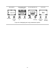
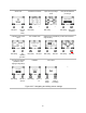
Sensor menu
Depending on the installed sensors, display screens may vary.
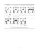
Control settings related to calibration and bump testing:
• Choose the "quick" or "standard" process for calibration and bump testing.
Quick process. This process allows for only one application of gas. It is well suited for installed sensor
combinations that use a calibration gas cylinder of the "blended" type—one that contains the gas types
and concentrations required for all installed sensors.
Standard process. This process allows for more than one application of gas. It provides time—between
sensors—for the change of cylinders. It is well suited for installed sensor combinations that require
more than one calibration gas cylinder.
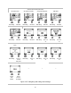
• Set calibration gas concentrations for each sensor and the correlation factor for an LEL sensor.
View the location of each installed sensor and its span reserve percentages. Note: An indicator of a
sensor's remaining life, the span reserve percentage will decline over time; when its value is less than 50%,
the sensor will no longer pass calibration.
Each sensor has a deadband value, which allows it to measure the low-level presence (or lack) of a gas,
but display a reading of zero. For example, if the deadband value for a CO sensor is 3 ppm, any positive
CO measurement up to and including +3 ppm will produce a display-screen reading of 0 ppm. Likewise, a
negative CO measurement down to and including -3 ppm will produce a reading of 0 ppm.
To allow the instrument to display as zero any gas measurements within the deadband, set the deadband
to on. To allow the instrument to display the sensor’s actual reading when the detected level of gas is within
the deadband, set the deadband to off.