
User Guide

Ref. 012002000200 Rev. 0: 02-09-2020
2
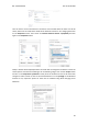
Switch Configuration
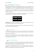
A Zone
For the Analog Shield if a switch is set to ON, it can only act as Digital Output. If it is set to OFF
it can only act as an Analog Output.
If it is desired to use a Digital Output the pin must be set to ON and the pin that will provide
this digital output is represented with QX.X, being X any number of the tables above.
If it is desired to use an Analog Output the pin must be set to OFF and the pin that will provide
this analog output is represented with AX.X, being X any number of the tables above.
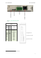
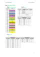
A Zone
Raspberry
PLC
Connector
I/Os I2C
1
Function
GND
A0.7
1
A0.6
1
A0.5
1
Q/Vdc
COM(-)
Q0.7
1
Q0.6
1
Q0.5
1
Q0.4
Q0.3
Q0.2
Q0.1
Q0.0
GND
-
-
-
-
-
-
-
-
-
-
-
-
-
GND
Analog Out
Analog Out
Analog Out
External Isolated Out Vdc
External Isolated Out GND
Digital/PWM Out
Digital/PWM Out
Digital/PWM Out
Digital Out
Digital Out
Digital Out
Digital Out
Digital Out
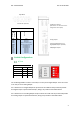
B ZONE
SWITCH
ON
OFF
NC
-
-
Q0.7
Q0.7
A0.7
Q0.6
Q0.6
A0.6
Q0.5
Q0.5
A0.5
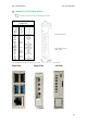
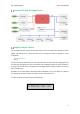
Led indicator I/Os state
Configuration Switch*
(See section 7 to select the correct
configuration for outputs).
Analog Outputs
Voltage Supply/Reference for
Digital/PWM Outputs (isolated)
PWM/Digital Outputs
Top Zone