
User's Manual


22
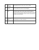
PRG -
Programming
port
micro-USB connector that allows flashing of the eMMC from a host
computer using balenaEtcher (balena.io/etcher) or usbboot. If the device
is powered via a cable connected to this port, it will enter a programming
mode exposing its eMMC as mass-storage to a host computer (via
balenaEtcher or usbboot). balenaFin can only be booted into flash mode
via this port
23
power in
polarity is denoted on PCB silkscreen
24
Barrel Jack
power in
2.1 / 5.5 mm barrel jack type connector for 6-24V input power. Positive
polarity (Positive tip, Negative sleeve) - Denoted by symbol on the
bottom PCB silkscreen.
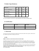
25
Co- Processor
I/O connector
8 x GPIO / ADC, 1 x SPI, 1 x I2C, 1 x Debug UART
26
CR122 RTC
coin-cell battery
socket
This allows the embedded RTC to keep track of time while the device is
powered off
27
RGB LED
Connected to a PCA9633 controller that allows standard linux sysfs LED
control
28
USB3 ON
Status LED
The green LED stays on as long as there is enough current flowing on
the 4-pin header USB port; when this LED is off, it means a fault or
under- voltage is happening on the 4-pin header USB port
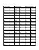
29
nano-SIM socket
This allows the use of a wide portfolio of cellular modems via the mPCIe
socket (32)
30
CM3L socket
SODIMM-200 socket for the Raspberry Pi Compute Module 3/3+ Lite
31
eMMC
8/16/32/64 GB class 5.1 industrial eMMC - main storage for the CM3L
(30). Positioned under the CM3L (30)
32
mPCIe
Mini PCI Express socket
33
Antenna switch
2 position switch - when set to OFF (labeled in silkscreen as "INT"), the
WiFi/BT combo chip (14) uses the WiFi/BT embedded antenna (16).
When set to ON (labeled in silkscreen as "EXT"), the WiFi/BT combo
chip
(14) uses the WiFi/BT uFL antenna connector (15)
34
PoE HAT
headers
exposes the incoming voltage from the RJ45 (21) port for PoE HATs that
step down and flow 5V to the 5V HAT (13) pins