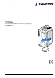
Communication Protocol Profibus DP/V1 Interface for Bayard-Alpert Pirani Capacitance Diaphragm Gauge BCG450-SP tira41e1 (2005-06) 1
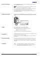
About this Document This document describes the functionality and programming of the Profibus interface of the BCG450-SP gauge. For safety information on and technical data of the gauges, please refer to the respective operating manuals (→ [1], [3]). In information referring to the ionization vacuum measuring part of the gauge, the short designation "BA" (Bayard-Alpert measuring principle) is used. The designation "Pirani" is used in information referring to the Pirani vacuum measuring part of the gauge.
Contents tira41e1 (2005-06) BCG450SPv1.cp About this Document Product Identification Validity Intended Use Functional Principle Trademarks 2 2 2 2 2 2 1 General Data 1.1 Data Rate 1.2 Device Address 1.3 Ident Number 1.4 Configuration Data 1.5 User Parameter Data 1.6 Types of Communication 5 5 5 5 5 6 6 2 Data Exchange Mode 2.1 Acyclic Data Transmission with Profibus DPV1 Functionality 2.2 Structure of the Cyclic Data Telegrams in Data Exchange Mode 2.2.1 Parameter Channel 2.2.1.
3.2.3.3 Data Type 3.2.3.4 Data Unit 3.2.3.5 Reading Valid 3.2.3.6 Full Scale 3.2.3.7 Safe State 3.2.3.8 Safe Value 3.2.3.9 Overrange 3.2.3.10 Underrange 3.2.4 Analog Sensor Input Function Block Instance 3 / SLOT 1 3.2.4.1 Process Value 3.2.4.2 Status 3.2.4.3 Data Type 3.2.4.4 Data Unit 3.2.4.5 Reading Valid 3.2.4.6 Full Scale 3.2.4.7 Safe State 3.2.4.8 Safe Value 3.2.4.9 Overrange 3.2.4.10 Underrange 3.2.5 Analog Sensor Input Function Block Instances 5 and 6 / SLOT 1 3.2.5.1 Process Value 3.2.5.2 Status 3.
1 General Data 1.1 Data Rate The gauge supports all data rates defined in the EN 50170 standard (→ [5]) up to 12 Mbaud. Automatic data rate setting is supported. Alternatively, a fixed data rate can be selected. 1.2 Device Address The device address ( node address) must be set via two rotary switches when the gauge is installed. For unambiguous identification of the gauge in a Profibus environment, a node address is required. The node address setting is made on the gauge.
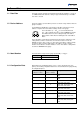
1.5 User Parameter Data Depending on the pressure unit setting ( data unit), the following configuration string has to be transmitted to the gauge (parameter data in hexadecimal format): Pressure unit User parameter data string COUNTS 1) 00 00 00 03 E9 Torr 00 00 00 05 15 Micron 00 00 00 05 16 mbar 00 00 00 05 1C Pascal 00 00 00 05 1D 1) 1.
2 Data Exchange Mode 2.1 Acyclic Data Transmission with Profibus DPV1 Functionality The reading and writing operations defined in Profibus are based on a slot index address scheme.
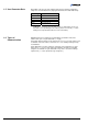
Assignment of the block elements to the slot indices Index Parameter_n Block_Type_Name Block_x Attributes Parameter_2 Parameter_1 Parameter_0 Operation_1 Operation_2 Operation_n 16 Public 0 2.2 Structure of the Cyclic Data Telegrams in Data Exchange Mode Operations Public optional optional Private In Data Exchange mode, the DP master class 1 cyclically transmits data from and to all slaves that are connected to the bus.
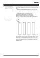
2.2.1 Parameter Channel The structure of the parameter channel is described in the table below. The parameter channel (called PKW Interface hereinafter) consists of 8 bytes. 1 2 Octets 4 5 3 PKE 6 IND res. 7 8 PWE The PKW Interface allows reading and writing of slave parameters with a maximum data length of 4 bytes. Strings cannot be read. The slave generates exactly one response per instruction transmitted by the master. The instruction and response cannot be blocked.
Instruction – response sequence 1) The master transmits an instruction to the slave and repeats that instruction until it receives a response from the slave. 2) The slave keeps transmitting the response to the instruction until the master transmits a new instruction. 3) The master marks the end of the first instruction cycle by setting AK to zero. Only after that, a new instruction/response cycle may be started. 2.2.1.2 PWE Parameter (Process Value) The PWE represents the data element to be transmitted.
2.3 Cyclic Message Telegrams The message telegrams listed below are implemented in the gauge. They can be selected according to requirements. When selecting a message telegram, ascertain what output format of the measured value (integer/float) is required and whether a parameter channel is needed or not. The gauge can also be operated in such a way that the master does not transmit any output data to the slave.
3 Block Model Data to the BCG450-SP can be transmitted by means of a number of communication protocols and corresponding masters. Profibus defines a master class 1 as normal control unit of the slave (typically a PLC) and a master class 2 as configuration and service unit. The following communication protocols are defined according to the Profibus DPV1 standard.
3.1 Device Block tira41e1 (2005-06) BCG450SPv1.cp The following table lists the services and parameters integrated in the Device Block (→ Appendix A for abbreviations).
3.1.1 Information on the Individual Indices 3.1.1.1 Block Type ID 16 The Block Type Parameter contains an ID which describes the block type. The block type ID of the Device Block 1. The other defined block types are listed in Appendix B. 3.1.1.2 Device Type ID 17 The Device Type identifies the device type which is connected to the field bus via Profibus. The Device Type of the BCG450-SP gauge is "CG", the abbreviation of "Combination Gauge". 3.1.1.
3.1.1.10 Exception Status ID 26 The Exception Status describes the alarm and warning states of the gauge in an "Expanded error output format". A difference is made between warnings and errors. Alarms and errors are divided into three groups (→ sections "Exception Detail Alarm" and "Exception Detail Warning" for details): • ALARM / Warning Device Common • ALARM / Warning Device Specific • ALARM / Warning Manufacturer Specific For errors that occur independently of the type of device used, e.g.
3.1.1.11 Exception Detail Alarm ID 27 If, in the Exception Status, one of the bits 0 … 2 is set, the current error can be read in the "Exception Detail Alarm" parameter. The "Exception Detail Alarm" parameter consists of a total of 12 bytes that inform on the error status of the gauge.
Device Exception Detail Alarm Bit Device Exception Detail 0 Referring to Capacitance diaphragm sensor tira41e1 (2005-06) BCG450SPv1.cp Device Exception Detail 1 Referring to Capacitance diaphragm sensor 0 Diaphragm Failure 0 0 1 0 1 Electronics/sensor error 2 0 2 0 3 0 3 0 4 0 4 0 5 0 5 0 6 0 6 0 7 0 7 0 This byte is a copy of Sensor Alarm byte 0 of Capacitance diaphragm sensor Transducer Block.
3.1.1.12 Exception Detail Warning ID 28 If, in the Exception Status, one of bits 4 … 6 is set, the current warning can be read in the parameter "Exception Detail Warning". The Exception Detail Warning parameter consists of a total of 13 bytes that inform on the error status of the gauge.
Common Exception Detail Warning Bit 0 Common Exception Detail 0 0 Bit 0 Common Exception Detail 1 0 1 0 1 0 2 EPROM exception 2 0 3 EPROM exception 3 0 4 RAM exception 4 0 5 0 5 0 6 0 6 0 7 0 7 0 The warning bits are set in the same way as the error bits because here, warnings have the same meaning as errors. Bit Device Exception Detail Warning Device Exception Detail 0 (2005-06) BCG450SPv1.
Bit Device Exception Detail 4 Referring to Pirani Bit Device Exception Detail 5 Referring to BA 0 0 0 0 1 Electronics/sensor warning Pirani 1 0 2 0 2 0 3 0 3 0 4 0 4 0 5 0 5 0 6 0 6 0 7 0 7 0 This byte is a copy of Sensor Warning byte 1 of the Heat Transfer Vacuum Gauge Transducer Block. Bit This byte is a copy of Sensor Warning byte 0 of the Hot Cathode Ion Gauge Transducer Block.
3.1.1.16 Copy Manufacturer Exception Detail Alarm 0 ID 207 This parameter corresponds to the Manufacturer Exception Detail Alarm Byte 0 of the Exception Detail Alarm (ID 27). 3.1.1.17 Copy Common Exception Detail Warning 0 ID 208 This parameter corresponds to the Common Exception Detail Warning Byte 0 of the Exception Detail Warning (ID 28). 3.1.1.
Device statuses 3.1.2.1 Device Block State Command Status name Description NORMAL The communication interface can respond to commands. All defined blocks of the gauge exist. RUNNING All block instances are initialized and the individual parameters have their initial or default values. SELFTESTING In this status, the gauge performs a selftest. IDLE All blocks defined in the gauge are initialized and the complete hardware has been tested and found free of errors.
3.2 Analog Input Block All gauge functions of the BCG450-SP are described in the Analog Input Block. Since the gauge includes three measuring systems, there are also three Analog Input Block Instances representing the Pirani measuring part, the ionization measuring part (BA) and the capacitance diaphragm gauge part (CDG) respectively. 3.2.
3.2.2 Analog Sensor Input Function Block Instance 1 / SLOT 1 3.2.2.1 Process Value Instance 1 of the Analog Sensor Input Function Blocks describes the functionality of the Pirani measuring part of the gauge.
3.2.2.4 Data Unit Coding Data type 3 Integer16 8 Float The gauge supports the following pressure units: Coding Data type 1001 COUNTS 1301 Torr 1302 mTorr (Micron) 1308 mbar 1309 Pascal For safety reasons, it is not possible to change the pressure unit while the gauge is cyclically interchanging data with a DP/V0 master. The data unit setting can only be modified when the gauge is in the IDLE status. In cyclic data traffic, the data unit must be set in the User Parameter Data.
3.2.2.7 Safe State When the gauge is not in the EXECUTING status (ID 25, Device Block) or if there is a device error, a value defined by Safe State is output as pressure value. You can select among: • "0" • Full scale • Last valid value • Safe Value (user-definable in ID 40) Safe State Coding PV behavior Zero 0 The Process Value (measured value ID 19) is set to 0. Full Scale 1 The Process Value (measured value ID 19) is set to the full scale value (ID 24).
3.2.3 Analog Sensor Input Function Block Instance 2 / SLOT 1 3.2.3.1 Process Value Instance 2 of the Analog Sensor Input Function Block describes the functionality of the BA measuring part of the gauge.
3.2.3.4 Data Unit The gauge supports the following pressure units: Coding Pressure unit 1001 COUNTS 1301 Torr 1302 mTorr (Micron) 1308 mbar 1309 Pascal For safety reasons, it is not possible to change the pressure unit while the gauge is cyclically interchanging data with a DP/V0 master. The data unit setting can only be modified when the gauge is in the IDLE status. In cyclic data traffic, the data unit must be set in the User Parameter Data.
Safe State Coding PV behavior Zero 0 The Process Value (measured value ID 19) is set to 0. Full Scale 1 The Process Value (measured value ID 19) is set to the full scale value (ID 24). Hold Last Value 2 The Process Value is set to the last valid value obtained in the EXECUTING status. Use Safe Value 3 The Process Value (measured value ID 19) is set to the Safe Value (ID 40). 3.2.3.
3.2.4 Analog Sensor Input Function Block Instance 3 / SLOT 1 3.2.4.1 Process Value Instance 3 of the Analog Sensor Input Function Block describes the functionality of the Capacitance diaphragm sensor measuring part of the gauge.
If the data type is set in one instance, that data type setting applies to all instances. Likewise, when a standard telegram is selected, the data type used by that standard telegram will be valid for all instances. 3.2.4.
3.2.4.7 Safe State When the gauge is not in the EXECUTING status (ID 25, Device Block) or if there is a device error, a value defined by Safe State is output as pressure value. You can select among: • "0" • Full scale • Last valid value • Safe Value (user-definable in ID 40) Safe State Coding PV behavior Zero 0 The Process Value (measured value ID 19) is set to 0. Full Scale 1 The Process Value (measured value ID 19) is set to the full scale value (ID 24).
3.2.5 Analog Sensor Input Function Block Instances 5 and 6 / SLOT 1 Instances 5 and 6 of the Analog Sensor Input Function Block describe the functionality of the two switching functions (Setpoint A / Setpoint B) of the gauge (setting the switching functions → [2], [3]): Instance Setpoint 5 A 6 B With Process Values (ID 19), the current threshold setting (made by means of the potentiometers) is read; with Status, the relay status (open/closed) can be read. 3.2.5.
3.2.5.2 Status If the pressure drops below the set threshold, the relay is activated (normally open contact closed). If the pressure then rises above the set threshold with a hysteresis of 10%, the relay is deactivated again (normally open contact open). Bit Definition 0 0 1 Low Alarm Exception: 0 = cleared, 1 = set 2 0 3 Low Warning Exception: 0 = cleared, 1 = set 4 0 5 0 6 0 7 0 3.2.5.3 Data Type Description → Instance 1. 3.2.5.4 Data Unit Description → Instance 1. 3.2.5.
Setpoint function "Atmosphere Control" Atmospheric pressure threshold Atmospheric pressure × N = ————————————— 100 Where: Atmospheric pressure threshold [mbar] : Atmospheric pressure N [mbar] : [%] : If the pressure inside the vacuum chamber rises above this threshold, the relay "Atmosheric pressure reached" is energized.
3.2.5.8 Atmosphere Reached If the Setpoint Function is set to Atmosphere Control and the relay is closed, this byte is set to one, if the relay is open or not energized, the value is zero. Additionally the following information is copied into the Manufacturer Exeption Detail Warning: • Bit 1 of Manufacturer Exeption Detail Warning is set if relay A is energized and atmospheric pressure is reached.
3.3.2.4 Sensor Warning This parameter indicates the detectable warnings occurring in connection with the Pirani measuring part. The present implementation allows detection of one warning. Bit7 Bit6 Bit5 Bit4 Bit3 Bit2 Bit1 Bit0 Byte 0 0 0 0 0 0 0 0 0 Byte 1 0 0 0 0 0 0 Electronics Warning 0 The Sensor Warning bits defined here are copied into the Device Block ID 28 in the "Device Exception Detail Warning" range of the Pirani measuring part. 3.3.
3.3.3.4 Sensor Warning This parameter indicates the detectable warnings occurring in connection with the BA measuring part. The present implementation allows detection of one warning. Bit7 Bit6 Bit5 Bit4 Bit3 Bit2 Bit1 Bit0 Byte 0 0 0 0 0 0 0 0 0 Byte 1 0 0 0 0 Pressure too high for degas 0 Electronics Warning 0 The Sensor Warning bits defined here are copied into the Device Block ID 28 in the "Device Exception Detail Warning" range of the BA measuring part. 3.3.3.
3.3.3.9 Hot Cathode Block State Command This service is used for activating the Degas mode via Profibus. Byte Name Structure Data type Bytes 0 State Command Simple Unsigned8 2 1 State Command Data Field Simple Unsigned8 1 2 Value Simple Unsigned8 1 State Command Name Description 0 Inactive No action 1 Set Degas State Activates/deactivates the Degas mode Access This service is used for activating/deactivating the Degas mode (p < 7.2×10⁻⁶ mbar).
3.3.4 Diaphragm Gauge Transducer Block / SLOT 1 / Instance 3 ID Name Structure Data type Bytes Access Store 101 Block Type Simple Octet string 4 2_R 102 Status Extension Simple UINT8 1 1/2_R V 103 Sensor Alarm Struct Array of 2 bytes 2 1/2_R V 104 Sensor Warning Struct Array of 2 bytes 2 1/2_R V 3.3.4.1 Block Type According to the table in Appendix A, the Block Type ID has the value "14". 3.3.4.
3.3.4 Atmosphere Sensor Transducer Block (Piezo Sensor) / SLOT 1 / Instance 4 ID Name 14 Atmosphere gauge Block State Command Structure Data type 101 Block Type REC Simple Octet string Bytes Access Store 2 1_W 2_W 4 2_R 3.3.4.1 Block Type The Block Type ID has the value: "01 00 00 00" (octet string). 3.3.4.2 Atmosphere Sensor Block State Command This service is used for activating the adjustment of the Piezo sensor to the Capacitance diaphragm sensor via Profibus.
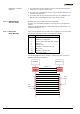
Appendix A: Definitions Data types Definitions Abbreviation 7 Data access 42 Data type 7 INT8 -2 … (2 - 1) Integer 1 byte INT16 -215 … (215 - 1) Integer 2 byte 31 31 INT32 -2 UINT8 0 … (28 - 1) Unsigned integer 1 byte UINT16 0 … (216 - 1) Unsigned integer 2 byte … (2 31 - 1) UINT32 0 … (2 FLOAT ±3.
Excerpts from: "PROFIBUS Profile for SEMI" (→ 4) tira41e1 (2005-06) BCG450SPv1.cp The following table explains terms used in connection with the Profibus. Term Meaning Alert Elements Alert Elements are used to communicate notification messages from slave to master when warnings, alarms or events are detected.
Excerpts from: "PROFIBUS Profile for SEMI" (cont.) 44 Term Meaning Function Block Application Application of an automation system performed by a Device Block, Function Block, Transducer Block and accompanied elements. Instance A set of data related to an invocation of a function block or a class. Internal Resolution (ir) The internal resolution is 16383 (3FFFhex) for 100% and -16384 (C000hex) for -100% of the range.
Appendix B: Block Type Currently defined Block Type IDs Block Name Block Type ID Device Block 1 Sensor Analog Input Function Block 2 One of N Channel Sensor Analog Input Function Block 3 Multi Channel Sensor Analog Input Function Block 4 Discrete Input Function Block 5 Actuation Analog Output Function Block 6 Discrete Output Function Block 7 Analog Output Function Block 8 Single Stage Controller Function Block 9 Gas Calibration Transducer Block 10 Flow Transducer Block 11 Sensor Ana
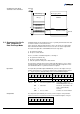
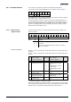
Appendix C: Electrical Connections Technical data of BCG450 gauges → Sensor cable connection [1], [2], [3]. ( Threshold values ) 1) SP A SP B 3 6 1 SP A 2) 4 9 SP B 2) 11 13 14 Degas 7 - Measuring signal Degas 2 - 12 + 1.25 AT 42 kΩ 8 Ident.
Profibus connection 1 5 D-Sub, 9 pins, male soldering side 6 Pin 1 Pin 2 Pin 3 Pin 4 Pin 5 Pin 6 Pin 7 Pin 8 Pin 9 tira41e1 (2005-06) BCG450SPv1.cp 9 not connected not connected RxD/TxD-P CNTR-P DGND VP not connected RxD/TxD-N not connected 1) 2) 2) 1) Only to be connected if an optical link module is used. 2) Only required as line termination for devices at both ends of bus cable [4]).
Appendix D: Literature 48 [1] www.inficon.com Instruction Sheet TripleGauge™, Bayard-Alpert Pirani Capacitance Diaphragm Gauge BCG450, BCG450-SD, BCG450-SP tima40e1 INFICON AG, LI–9496 Balzers, Liechtenstein [2] www.inficon.com Instruction Sheet TripleGauge™, Bayard-Alpert Pirani Capacitance Diaphragm Gauge BCG450-SD, BCG450-SP tima41e1 INFICON AG, LI–9496 Balzers, Liechtenstein [3] www.inficon.
Notes tira41e1 (2005-06) BCG450SPv1.
Notes 50 tira41e1 (2005-06) BCG450SPv1.
Notes tira41e1 (2005-06) BCG450SPv1.
Original: German tira41d1 (2005-06) t i r a41e1 LI–9496 Balzers Liechtenstein Tel +423 / 388 3111 Fax +423 / 388 3700 reachus@inficon.com www.inficon.