
User Manual
Bayard Alpert Pirani Gauge
With Fieldbus Interface
BPG400-SD, BPG400-SP, BPG400-SR
RS485
Instruction Sheet
tima36e1-b (2004-02)
About this document
This document is a supplement to the standard Instruction
Sheet enclosed with the BPG400 ( [1]). It should be used
together with the standard Instruction Sheet.
The symbol (→ [XY]) refers to documents and files
listed under "Further Information".
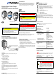
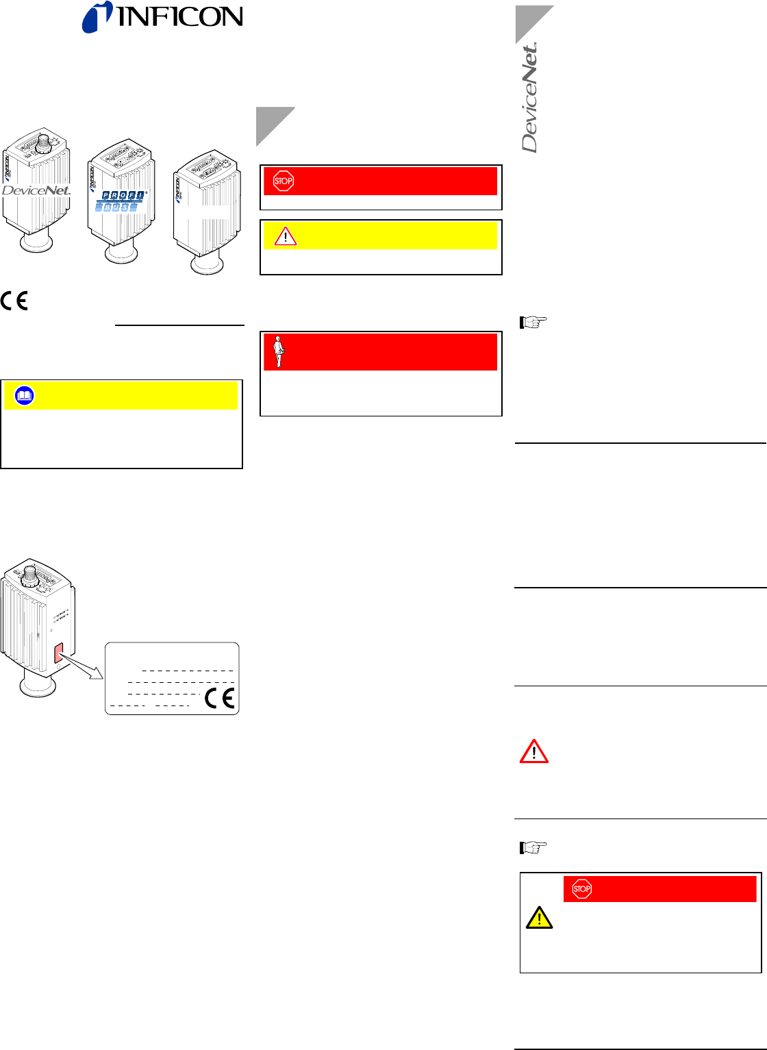
Product Identification
In all communications with INFICON, please specify the in-
formation on the product nameplate. For convenient refer-
ence copy that information into the space provided below.
Model:
PN:
SN:
V W
INFICON AG, LI-9496 Balzers
Validity
This document applies to products with the following part
numbers:
BPG400-SD (DeviceNet):
353-507
(DN 25 ISO-KF)
353-508 (DN 40 CF-R)
BPG400-SP (Profibus):
353-505
(DN 25 ISO-KF)
353-506 (DN 40 CF-R)
BPG400-SR (RS485):
353-509
(DN 25 ISO-KF)
353-513 (DN 40 CF-R)
The part number (PN) can be taken from the product
nameplate.
If not indicated otherwise in the legends, the illustrations in
this document correspond to the vacuum connection
DN 25 ISO-KF. They apply to other vacuum connections by
analogy.
We reserve the right to make technical changes without prior
notice.
All dimensions in mm.
Trademarks
DeviceNet™ Open DeviceNet Vendor Association, Inc.
Intended Use
The Bayard Alpert Pirani Gauges of the type BPG400-SD,
BPG400-SP and BPG400-SR have been designed for
vacuum measurement of non-flammable gases and gas
mixtures in a pressure range of 5×10
-10
... 1000 mbar.
Safety
Symbols Used
DANGER
Information on preventing any kind of physical injury.
Caution
Information on correct handling or use. Disregard can lead
to malfunctions or minor equipment damage.
Personnel Qualifications
Skilled personnel
All work described in this document may only be carried out
by persons who have suitable technical training and the
necessary experience or who have been instructed by the
end-user of the product.
General Safety Instructions
All safety instructions given in [1] and [2] apply to the
sensor types described in this document, too.
Liability and Warranty
INFICON assumes no liability and the warranty becomes null
and void if the end-user or third parties
• disregard the information in this document
• use the product in a non-conforming manner
• make any kind of changes (modifications, alterations etc.)
to the product
• use the product with accessories not listed in the product
documentation.
The end-user assumes the responsibility in conjunction with
the process media used.
BPG400-SD (DeviceNet)
General Information
The BPG400-SD gauge has a fieldbus interface that
conforms to the DeviceNet standard (→ [8]).
Via this interface, the following and further data are
exchanged in the standardized DeviceNet Protocol
(→ [3], [8]):
• Pressure reading
• Pressure unit (Torr, mbar, Pa)
• Degas function
• Gauge adjustment
• Status and error messages
Two adjustable switching functions are integrated in the
gauge. The corresponding relay contacts are available at the
sensor cable connector.
The basic sensor and sensor electronics of the BPG400-SD
type are the same as in the standard BPG400 (→ [1], [2]).
Technical Data
General technical data of the sensor and sensor
electronics → [1], [2]
Fieldbus Interface
Fieldbus name DeviceNet
Standard applied
→ [8]
Communication protocol,
data format
→ [3], [8]
Interface, physical CAN bus
DeviceNet Parameters
Data rate (adjustable via
"RATE" switch)
125 kBaud
250 kBaud
500 kBaud
"P" (programmable
125 kBaud, 250 kBaud,
500 kBaud via DeviceNet
(→ [3])
Node address (MAC ID)
(adjustable via "ADDRESS,
MSD, LSD" switches)
0 … 63
dec
"P" (programmable
0 … 63 via DeviceNet)
(→ [3])
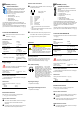
DeviceNet connector Micro-Style, 5 pins, male
Cable Shielded special
DeviceNet cable,
5 conductors (→ [8],
[6])
Cable length, system wiring According to DeviceNet
specifications (→ [8],
[6])
Supply Voltages
The power consumption of the BPG400-SP is higher
than that of the standard BPG400 (→ [1], [2]).
Supply voltage at the sensor
connector, Pin 8 +24 VDC (+20 … 28 V)
Power consumption <18 W
DeviceNet operation requires an additional, separate
power supply.
DANGER
The gauge may only be connected to power
supplies, instruments or control devices that
conform to the requirements of a grounded pro-
tective extra-low voltage (SELV-E according to
EN 61010). The connection to the gauge has to
be fused.
Supply voltage at the DeviceNet
connector, Pin 2 +24 VDC (+11 … 25 V)
Power consumption <2 W
The gauge is protected from reversed polarity of the supply
voltage.