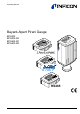
Operating Manual Bayard-Alpert Pirani Gauge BPG400 BPG400-SD BPG400-SP BPG400-SR RS485 tina03e1-b (2004-02) 1
Product Identification In all communications with INFICON, please specify the information on the product nameplate. For convenient reference copy that information into the space provided below.
Functional Principle Over the whole measuring range, the gauge has a continuous characteristic curve and its measuring signal is output as logarithm of the pressure. The gauge functions with a Bayard-Alpert hot cathode ionization measurement system (for p < 2.0×10⁻² mbar) and a Pirani measurement system (for p > 5.5×10⁻³ mbar). In the overlapping pressure range of 2.0×10⁻² … 5.5×10⁻³ mbar, a mixed signal of the two measurement systems is output.
Contents 4 Product Identification Validity Intended Use Functional Principle Trademarks 2 2 2 3 3 1 Safety 1.1 Symbols Used 1.2 Personnel Qualifications 1.3 General Safety Instructions 1.4 Liability and Warranty 6 6 6 7 7 2 Technical Data 8 3 Installation 3.1 Vacuum Connection 3.1.1 Removing and Installing the Electronics Unit 3.1.2 Installing the Optional Extension 3.1.3 Using the Optional Baffle 3.2 Electrical Connection 3.2.1 Use With INFICON VGC103 or VGC40x Vacuum Gauge Controller 3.2.
Deinstallation 46 6 Maintenance, Repair 6.1 Maintenance 6.1.1 Cleaning the Gauge 6.2 Adjusting the Gauge 6.2.1 Adjustment at Atmospheric Pressure 6.2.2 Zero Point Adjustment 6.3 What to Do in Case of Problems 6.
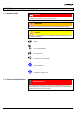
1 Safety 1.1 Symbols Used DANGER Information on preventing any kind of physical injury. WARNING Information on preventing extensive equipment and environmental damage. Caution Information on correct handling or use. Disregard can lead to malfunctions or minor equipment damage. Notice Hint, recommendation The result is O.K. The result is not as expected Optical inspection Waiting time, reaction time 1.
1.3 General Safety Instructions • Adhere to the applicable regulations and take the necessary precautions for the process media used. Consider possible reactions between the materials (→ 11) and the process media. Consider possible reactions of the process media (e.g. explosion) due to the heat generated by the product. • Adhere to the applicable regulations and take the necessary precautions for all work you are going to do and consider the safety instructions in this document.
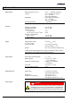
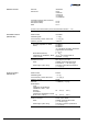
2 Technical Data Measurement Measuring range (air, N2, O2) Accuracy Repeatability Gas type dependence Emission Degas Switching on threshold Switching off threshold Emission current -6 p ≤7.2×10 mbar -6 7.2×10 mbar
Operating voltage at the gauge Power consumption Standard Degas Emission start (<200 ms) Power consumption BPG400 BPG400-SD, -SP, -SR Fuse necessary +24 VDC (20 … 28 VDC) 1) ripple max. 2 Vpp ≤0.5 A ≤0.8 A ≤1.4 A ≤16 W ≤18 W 1.25 AT BPG400-SD requires an additional, separate power supply for the DeviceNet interface (→ 22). Supply voltage at the DeviceNet connector, (Pin 2 and Pin 3) +24 VDC (+11 … 25 VDC) Power consumption <2 W The gauge is protected against reversed polarity of the supply voltage.
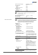
RS232C interface Data rate Data format Connections (sensor cable connector) TxD (Transmit Data) RxD (Receive Data) GND 9600 Baud binary 8 data bits one stop bit no parity bit no handshake Pin 13 Pin 14 Pin 5 (Function and communication protocol of the RS232C interface → DeviceNet interface (BPG400-SD) Fieldbus name Standard applied DeviceNet Communication protocol, data format → [1], [4] CAN bus Interface, physical → 31) [6] Data rate (adjustable via "RATE" switch) 125 kBaud 250 kBaud 500 kBa
RS485 interface (BPG400-SR) Fieldbus name Data rate Device address (Adjustable via hexadecimal "ADDRESS", "MSD", "LSD" switches) RS485 300 … 28'800 Baud RS485 connection Cable D-Sub, 9 pins, male Cable length Vacuum Weight Ambiance Materials exposed to vacuum Housing, supports, screens Feedthroughs Insulator Cathode Cathode holder Pirani element Internal volume DN 25 ISO-KF DN 40 CF-R ≈290 g ≈550 g ≈430 g ≈695 g Type of protection BPG400 v1.
Dimensions Part number 353-500 353-501 353-505 353-509 1) (353-507) Part number 353-502 353-503 353-506 353-513 (353-508) 1) 4-40UNC 2B DN 25 ISO-KF 1) 4-40UNC 2B DN 40 CF-R Gauges with DeviceNet connector are 14 mm longer. The other dimensions of housing and vacuum connection are identical. Part number 353-507 353-508 12 tina03e1-b (2004-02) BPG400 v1.
3 Installation 3.1 Vacuum Connection DANGER Caution: overpressure in the vacuum system >1 bar Injury caused by released parts and harm caused by escaping process gases can result if clamps are opened while the vacuum system is pressurized. Do not open any clamps while the vacuum system is pressurized. Use the type of clamps which are suited to overpressure. DANGER The gauge must be electrically connected to the grounded vacuum chamber.
Make the flange connection to the vacuum system, preferably without applying vacuum grease. When installing the gauge, make sure that the area around the connector is accessible for the tools required for adjustment while the gauge is mounted (→ 44, 47). When installing the gauge, allow for installing/deinstalling the connectors and accommodation of cable loops. If you are using a gauge with display, make sure easy reading of the display is possible. The gauge is now installed. 3.1.
Remove the electronics unit without twisting it. Removal of the electronics unit is completed. Installing the electronics unit Place the electronics unit on the sensor (3) (be careful to correctly align the pins and notch (4)). 4 3 Slide the electronics unit in to the mechanical stop and lock it with the hexagon socket set screw (1). The electronics unit is now installed. tina03e1-b (2004-02) BPG400 v1.
3.1.2 Installing the Optional Extension With the optional extension (→ 52) the sensor can also be baked during operation at temperatures up to 150 °C (only at p<10-2 mbar because at high temperatures, the accuracy of the Pirani sensor decreases). Caution Caution: rising heat The electronics unit of gauges that are installed vertically, above the source of heat can be damaged through rising heat even with an installed extension.
Slide the electronics unit (2) in to the mechanical stop (be careful to correctly align the pins and notch (4a)). Secure the electronics unit (2) with the hex socket set screw (1) using an Allen key, size 2.5 mm. The extension is now installed. 3.1.
Carefully place the baffle onto the sensor opening. Using a pin, press the baffle down in the center until it catches. The baffle is now installed (Installation of the gauge → Deinstallation 13). Using a pin, press the baffle down in the center until it catches. The new baffle is now installed (Installation of the gauge → 18 13). tina03e1-b (2004-02) BPG400 v1.
3.2 Electrical Connection 3.2.1 Use With INFICON VGC103 or VGC40x Vacuum Gauge Controller If the gauge is used with an INFICON VGC103 or VGC40x controller, a corresponding sensor cable is required (→ [10]). The sensor cable permits supplying the gauge with power, transmitting measurement values and gauge statuses, and making parameter settings.
3.2.2.1 Making an Individual Sensor Cable Cable type For reasons of compatibility, the expression "sensor cable" is used for all BPG400 versions in this document, although the pressure reading of the gauges with fieldbus interface (BPG400-SD, BPG400-SP or BPG400-SR) is normally transmitted via DeviceNet, Profibus or RS485. The sensor cable is required for supplying all BPG400 types with power.
Sensor cable connection BPG400-SD, -SP, -SR BPG400-SD, BPG400-SP, BPG400-SR Threshold value, SP A 3 Threshold value, SP B 6 1 SP A 4 9 SP B 11 TxD 13 RxD 14 Degas 7 +Ub 8 Measuring signal 2 RS232 Degas 1.25 AT 24V 12 42 kΩ 5 10 Identification 15 Electrical connection Pin 1 Relay Switching function A, COM contact Pin 2 Signal output (measuring signal) 0 … +10 V Pin 3 Threshold value (Setpoint) A 0 … +10 V Pin 4 Relay Switching function A, N.O.
Plug the sensor connector into the gauge and secure it with the locking screws. Connect the other end of the sensor cable to the connector of the instrument or gauge controller you are using. The gauge can now be operated via analog and RS232C interface. 3.2.2.2 Making a DeviceNet Interface Cable (BPG400-SD) Cable type For operating BPG400-SD via DeviceNet, an interface cable conforming to the DeviceNet standard is required. If no such cable is available, make one according to the following indications.
Plug the DeviceNet (and sensor) cable connector into the gauge. DeviceNet cable Sensor cable Lock the DeviceNet (and sensor) cable connector. The gauge can now be operated via DeviceNet interface (→ 3.2.2.3 Making a Profibus Interface Cable (BPG400-SP) Cable type 34). For operating BPG400-SP via Profibus, an interface cable conforming to the Profibus standard is required. If no such cable is available, make one according to the following indications.
Plug the Profibus (and sensor) cable connector into the gauge. Sensor cable Profibus cable Lock the Profibus (and sensor) cable connector. The gauge can now be operated via Profibus interface (→ 3.2.2.4 Making a RS485 Interface Cable (BPG400-SR) Cable type Procedure 36). For operating BPG400-SR via RS485 bus, a suitable interface cable is required. If no such cable is available, make one according to the following indications.
Plug the RS485 (and sensor) cable connector into the gauge. Sensor cable RS485 cable Lock the RS485 (and sensor) cable connector. The gauge can now be operated via RS485 interface (→ 3.2.3 Using the Optional Power Supply (With RS232C Line) Technical data 37). The optional 24 V power supply (→ 52) allows RS232C operation of the BPG400 gauge with any suitable instrument or control device (e.g. PC).
Connecting the power supply Connect the gauge to the power supply and lock the connector with the screws. Connect the RS232C line to the instrument or control device and lock the connector with the screws. PC RS232C Power supply Mains BPG400 Connect the power supply to the mains. Turn the power supply on. The gauge can now be operated via RS232C interface (→ 26 31). tina03e1-b (2004-02) BPG400 v1.
4 Operation 4.1 Measuring Principle, Measuring Behavior Bayard-Alpert The BPG400 vacuum gauges consist of two separate measuring systems (hot cathode Bayard-Alpert (BA) and Pirani). The BA measuring system uses an electrode system according to Bayard-Alpert which is designed for a low x-ray limit. The measuring principle of this measuring system is based on gas ionization. Electrons emitted by the hot cathode (F) ionize a number of molecules proportional to the pressure in the measuring chamber.
Schematic UB Pirani sensor The bridge voltage UB is a measure for the gas pressure and is further processed electronically (linearization, conversion). Measuring range The BPG400 gauges continuously cover the measuring range 5×10⁻¹⁰ mbar … 1000 mbar. • The Pirani constantly monitors the pressure. • The hot cathode (controlled by the Pirani) is activated only at pressures <2.4×10⁻² mbar.
4.3 Putting the Gauge Into Operation When the operating voltage is supplied (→ Technical Data), the output signal is available between Pin 2 (+) and Pin 12 (–) of the sensor cable connector (Relationship Output Signal – Pressure → Appendix A). Allow for a stabilizing time of approx. 10 min. Once the gauge has been switched on, permanently leave it on irrespective of the pressure. Communication via the digital interfaces is described in separate sections. 4.
4.5 Display (BPG400) The gauges with part number 353-501 and 353-503 have a built-in two-line display with an LCD matrix of 32×16 pixels. The first line shows the pressure, the second line the pressure unit, the function and possible errors. The background illumination is usually green, in the event of an error, it changes to red. The pressure is displayed in mbar (default), Torr or Pa. The pressure unit can be changed via RS232C interface (→ 31).
4.6 RS232C Interface The built-in RS232C interface allows transmission of digital measurement data and instrument conditions as well as the setting of instrument parameters. Caution Caution: data transmission errors If the gauge is operated with the RS232C interface and a fieldbus interface at the same time, data transmission errors may occur. The gauge must not be operated with the RS232C interface and DeviceNet, Profibus or RS485 at the same time. 4.6.
Status byte Bit 1 Bit 0 0 0 0 1 1 1 0 1 Bit 2 Emission 25 µA Emission 5 mA Degas 1000 mbar adjustment off 1000 mbar adjustment on Bit 3 Definition 0⇔1 Software version Emission off Definition 0 1 Error byte Definition Toggle bit, changes with every string received correctly Bit 5 Bit 4 Definition 0 0 1 0 1 0 Bit 7 Bit 6 Definition x x Not used Bit 3 Bit 2 Bit 1 Bit 0 Definition x x x x Not used Bit 7 Bit 6 Bit 5 Bit 4 Definition 0 1 1 1 0 0 0 0 0 1 0 1 Curren
Example The example is based on the following output string: Byte No 0 1 2 3 4 5 6 7 8 Value 7 5 0 0 242 48 20 10 69 The instrument or controller (receiver) interprets this string as follows: Byte No Function 0 1 2 3 4 5 6 7 8 4.6.1.2 Input String (Receive) Format of the input string Length of data string Page number Status Error Measurement High byte Low byte Software version Sensor type Check sum Byte no 1) (2004-02) BPG400 v1.
4.7 DeviceNet Interface (BPG400-SD) This interface allows operation of BPG400-SD with part number 353-507 and 353-508 in connection with other devices that are suited for DeviceNet operation. The physical interface and communication firmware of BPG400-SD comply with the [4], [6]). DeviceNet standard (→ Two adjustable switching functions are integrated in BPG400-SD. The corresponding relay contacts are available at the sensor cable connector (→ 8, 21, 44).
4.7.2.3 Data Rate Setting The admissible data rate depends on a number of factors such as system pa[4], [6]). It can be set on the gauge or prorameters and cable length → grammed via DeviceNet. By means of the "RATE" switch, the data rate can be set to 125 ("1"), 250 ("2") or 500 kBaud ("5"). If the switch is in any of the "P" positions, the data rate is pro[1]). grammable via DeviceNet (→ 4.7.
4.8 Profibus Interface (BPG400-SP) This interface allows operation of BPG400-SP with part number 353-505 and 353-506 in connection with other devices that are suited for Profibus operation. The physical interface and communication firmware of BPG400-SP comply with the Profibus [7], [5]. standard (→ Two adjustable switching functions are integrated in the BPG400-SP. The corresponding relay contacts are available at the sensor cable connector (→ 8, 21, 44).
4.9 RS485 Interface (BPG400-SR) This interface allows operation of BPG400-SR with part number 353-509 and 353-513 in connection with other devices that are suited for RS485 bus operation. Two adjustable switching functions are integrated in BPG400-SR. The corresponding relay contacts are available on the sensor cable connector (→ 21). Additionally, the relay contact of the switching function A is accessible on the RS485 interface connector (→ 24).
4.9.2.2 Device Address For unambiguous identification of the gauge in a RS485 bus environment, a device address is required. The device address (base address) setting is primarily made on the gauge.
4.9.3 Syntax Description 4.9.3.1 Definitions, Legend In the table "Commands and Responses" (→ used: Variable 40) the following variables are Description Values, range, aa Operating device address 00 … 3Fhex fff Emission current _25UA 5.
4.9.3.2 Commands and Responses The following table lists all permissible commands of the RS485 host and the corresponding responses of a BPG400 SR during data transfer. Depending on the operation mode selected (BPG or RIG mode) the BPG400-SR responses may differ. Syntax errors will produce an error message.
"Commands and Responses" continued: Host Command Host Command syntax Set + threshold (Setpoint A) #aaSL+x.xxEsyy CR *aa_PROGM_OK CR (*aa_zMIN_HYS CR) → BPG mode T: #02SL+1.00E–04 CR R: *02_PROGM_OK CR Set – threshold (Setpoint A) #aaSL–x.xxEsyy CR *aa_PROGM_OK CR (*aa_zMIN_HYS CR) → BPG mode T: #02SL–2.00E–04 CR R: *02_PROGM_OK CR (SL+ ≠ SL–) Read + threshold (Setpoint A) #aaRL+x.xxEsyy CR *aa_PROGM_OK CR → BPG mode Read – threshold (Setpoint A) #aaRL–x.
4.9.4 Switching Functions The BPG400-SR has two independent switching functions. A floating relay contact is available for each switching function (→ 21). Additionally, the relay contact of the switching function A is accessible on the RS485 interface connector (→ 24). The functionality of the switching functions (setting of thresholds and relay operation) depends on the gauges threshold potentiometer settings: Selecting the Source of the Threshold Values Threshold potentiometer setting ≤0.
4.9.4.1 Programming the Switching Functions The programming procedure of the switching functions via the RS485 interface implemented in the BPG400-SR differs from the one used on BPG400-SD/SP. The table below describes the programming possibilities. Threshold values, relay operation Function Programming example (→ table, 40) Pressure p su Mea ue red val SL Hysteresis Relay SL + Off SL+ < SL– ⇒ relay on below SL+ T: #02SL+1.00E–04 CR R: *02_PROGM_OK CR T: #02SL–2.
4.10 Switching Functions (BPG400-SD, -SP, -SR) The gauges BPG400-SD, BPG400-SP and BPG400-SR have two independent, manually settable switching functions. Each switching function has a floating normally open relay contact. The relay contacts are accessible at the sensor cable connector (→ 21). On the BPG400-SR, the change over relay contact of setpoint A is also accessible at the RS485 interface connector (→ 24).
Procedure The procedure for setting thresholds is identical for both switching functions. Put the gauge into operation. Connect the + lead of a voltmeter to the threshold measurement point of the selected switching function ("Setpoint A" Pin 3, "Setpoint B" Pin 6) and its – lead to Pin 5. Setpoint A Pin 3 Setpoint B Pin 6 Pin 5 max. ø2.5 Using a screwdriver (max. ø2.5 mm), set the voltage of the selected switching function (Setpoint A, B) to the desired value UThreshold.
5 Deinstallation DANGER Caution: contaminated parts Contaminated parts can be detrimental to health and environment. Before beginning to work, find out whether any parts are contaminated. Adhere to the relevant regulations and take the necessary precautions when handling contaminated parts. Caution Caution: vacuum component Dirt and damages impair the function of the vacuum component. When handling vacuum components, take appropriate measures to ensure cleanliness and prevent damages.
6 Maintenance, Repair 6.1 Maintenance DANGER Caution: contaminated parts Contaminated parts can be detrimental to health and environment. Before beginning to work, find out whether any parts are contaminated. Adhere to the relevant regulations and take the necessary precautions when handling contaminated parts. 6.1.1 Cleaning the Gauge Small deposits on the electrode system can be removed by baking the anode (Degas → 29). In the case of severe contamination, the baffle can be exchanged easily (→ 17).
Required tools • Procedure Gauges BPG400-SD, -SP and -SR are mechanically slightly different from the BPG400. The adjustment opening of BPG400-SD, -SP and -SR is on one side of the gauge housing. However, the adjustment procedure is the same for all gauge versions. Pin approx. ø1.3 × 50 mm (e.g. a bent open paper clip) Operate gauge for approx. 10 minutes at atmospheric pressure. If the gauge was operated before in the BA range, a coolingdown time of approx.
Required tools • Procedure The push button used for the adjustment at atmospheric pressure is also used for the zero point adjustment (→ 47). Pin approx. ø1.3 × 50 mm (e.g. a bent open paper clip) Operate gauge for approx. 10 minutes at a pressure of ≤1×10⁻⁴ mbar. Insert the pin through the opening and push the button inside for at least 2 s. The adjustment is done automatically and ends after 2 minutes. The zero point of the gauge is now adjusted. 6.
Troubleshooting (sensor) If the cause of a fault is suspected to be in the sensor, the following checks can be made with an ohmmeter (the vacuum system need not be vented for this purpose). Separate the sensor from the electronics unit (→ the following measurements on the contact pins. Ohmmeter measurement between pins 14). Using an ohmmeter, make Possible cause ≈37 Ω 2+4 >>37 Ω Pirani element 1 broken >>37 Ω Pirani element 2 broken ≈37 Ω ≈0.15 Ω >>0.
6.4 Replacing the Sensor Required tools / material Replacement is necessary, when • the sensor is severely contaminated • the sensor is mechanically deformed • the sensor is faulty, e.g. filament of hot cathode broken (→ • the sensor is faulty, e.g. Pirani element broken (→ • Allen key, size 2.5 mm • Spare sensor (→ 49) 49) 52) Procedure Deinstall the gauge (→ 46). Deinstall the electronics unit from the faulty sensor and mount it to the new sensor (→ 14). Adjust the gauge (→ 47).
7 Options Part number 24 VDC power supply / RS232C line (→ Extension 100 mm (→ 353-511 25) 353-510 16) Baffle DN 25 ISO-KF / DN 40 CF-R (→ 353-512 17) 8 Spare Parts When ordering spare parts, always indicate: • All information on the product nameplate • Description and part number Part number Replacement sensor BPG400, vacuum connection DN 25 ISO-KF (including Allen key) Replacement sensor BPG400, vacuum connection DN 40 CF-R (including Allen key) 354-490 354-491 9 Storage Caution Caution: vac
10 Returning the Product WARNING Caution: forwarding contaminated products Contaminated products (e.g. radioactive, toxic, caustic or biological hazard) can be detrimental to health and environment. Products returned to INFICON should preferably be free of harmful substances. Adhere to the forwarding regulations of all involved countries and forwarding companies and enclose a duly completed declaration of contamination (→ 58).
Appendix A: Relationship Output Signal – Pressure p = 10(U - 7.75) / 0.75 + c Conversion formulae U = 0.75 × (log p - c) + 7.75 where Conversion curve U p c [V] [V] [V] [mbar] [Pa] [Torr] 0 2 -0.125 Pressure p [mbar] 1E+04 1E+03 1E+02 1E+01 1E+00 1E–03 1E–04 1E–05 Inadmissible range 1E–02 Sensor error Inadmissible range 1E–01 1E–06 1E–07 1E–08 1E–09 1E–10 0.0 1.0 2.0 3.0 4.0 5.0 6.0 7.0 8.0 9.0 10.0 Measuring signal U[V] 54 tina03e1-b (2004-02) BPG400 v1.
Conversion table Output signal U [V] Pressure p [Torr] [mbar] Sensor error (→ 49) Inadmissible range 3.75×10⁻¹⁰ 7.5×10⁻¹⁰ 7.5×10⁻⁹ 7.5×10⁻⁸ 7.5×10⁻⁷ 7.5×10⁻⁶ 7.5×10⁻⁵ 7.5×10⁻⁴ 7.5×10⁻³ 7.5×10⁻² 7.5×10⁻¹ 7.5×100 7.5×101 7.5×10² Inadmissible range 0.3 / 0.5 0.51 … 0.774 0.774 1.00 1.75 2.5 3.25 4.00 4.75 5.50 6.25 7.00 7.75 8.50 9.25 10.00 >10.
Calibration in pressure range 10-2 … 1 mbar The gas type dependence in the pressure range 10-2 … 1 mbar can be compensated by means of the following formula: peff = C × indicated pressure where Gas type Calibration factor C Air, O2, CO N2 CO2 Water vapor Freon 12 H2 He Ne Ar Kr Xe 1.0 0.9 0.5 0.7 1.0 0.5 0.8 1.4 1.7 2.4 3.0 (The above calibration factors are mean values.
C: tina03e1-b Literature (2004-02) BPG400 v1.om [1] www.inficon.com Communication Protocol DeviceNet™ BPG400-SD tira03e1 INFICON AG, LI–9496 Balzers, Liechtenstein [2] www.inficon.com Communication Protocol Profibus BPG400-SP tira36e1 INFICON AG, LI–9496 Balzers, Liechtenstein [3] www.inficon.com Product descriptions and downloads INFICON AG, LI–9496 Balzers, Liechtenstein [4] www.odva.org Open DeviceNet Vendor Association, Inc. DeviceNet™ Specifications [5] www.profibus.
Declaration of Contamination The service, repair, and/or disposal of vacuum equipment and components will only be carried out if a correctly completed declaration has been submitted. Non-completion will result in delay. This declaration may only be completed (in block letters) and signed by authorized and qualified staff. Description of product Reason for return Type Part number Serial number Operating fluid(s) used (Must be drained before shipping.
Notes tina03e1-b (2004-02) BPG400 v1.
Original: German tina03d1-b (2004-02) t i na03e1- b LI–9496 Balzers Liechtenstein Tel +423 / 388 3111 Fax +423 / 388 3700 reachus@inficon.com www.inficon.