
User Manual


tina03e1-b (2004-02) BPG400 v1.om 27
4 Operation
The BPG400 vacuum gauges consist of two separate measuring systems (hot
cathode Bayard-Alpert (BA) and Pirani).
The BA measuring system uses an electrode system according to Bayard-Alpert
which is designed for a low x-ray limit.
The measuring principle of this measuring system is based on gas ionization. Elec-
trons emitted by the hot cathode (F) ionize a number of molecules proportional to
the pressure in the measuring chamber. The ion collector (IC) collects the thus
generated ion current I
+
and feeds it to the electrometer amplifier of the measure-
ment instrument. The ion current is dependent upon the emission current I
e
, the
gas type, and the gas pressure p according to the following relationship:
I
+
= I
e
× p × C
Factor C represents the sensitivity of the gauge head. It is generally specified for
N
2
.
The lower measurement limit is 5×10
-10
mbar (gauge metal sealed).
To usefully cover the whole range of 5×10
-10
mbar … 10
-2
mbar, a low emission
current is used in the high pressure range (fine vacuum) and a high emission cur-
rent is used in the low pressure range (high vacuum). The switching of the emis-
sion current takes place at decreasing pressure at approx. 7.2×10
-6
mbar, at in-
creasing pressure at approx. 3.2×10
-5
mbar. At the switching threshold, the
BPG400 can temporarily (<2 s) deviate from the specified accuracy.
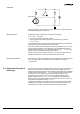
Diagram of the BA measuring system
F hot cathode (filament)
IC ion collector
EC anode (electron collector)
IC
200V40V
+– +–
(Degas 250V)
ECF
F
EC
IC
Within certain limits, the thermal conductibility of gases is pressure dependent. This
physical phenomenon is used for pressure measurement in the thermal conduc-
tance vacuum meter according to Pirani. A self-adjusting bridge is used as
measuring circuit (
→ schematic). A thin tungsten wire forms the sensor element.
Wire resistance and thus temperature are kept constant through a suitable control
circuit. The electric power supplied to the wire is a measure for the thermal con-
ductance and thus the gas pressure. The basic principle of the self-adjusting bridge
circuit is shown in the following schematic.
4.1 Measuring Principle,
Measuring Behavior
Bayard-Alpert
Pirani