Communication Protocol EtherCAT® for Bayard-Alpert Pirani Gauge BPG402-SE tira93e1 (2014-04) 1
General Information Caution Caution: data transmission errors Any attempt to simultaneously operate the gauge via the RS232C Serial Interface and EtherCAT interface may result in incorrect data and data transmission errors. Therefore, it is inadmissible to simultaneously operate the gauge via the RS232C Serial Interface and EtherCAT interface. Intended Use This Communication Protocol contains instructions for operating EtherCAT interfaces (slaves) together with a master.
Validity This document applies to BPG402 with EtherCAT interface. 353-590 353-591 (DN 25 ISO-KF) (DN 40 CF-R) The part number (PN) can be taken from the product nameplate. If not indicated otherwise in the legends, the illustrations in this document correspond to the gauges with vacuum connection DN 25 ISO-KF. They apply to gauges with the other vacuum connection by analogy. We reserve the right to make technical changes without prior notice. Trademark tira93e1 (2014-04) BPG402-SE.
Contents General Information Intended Use EtherCAT–Interface Product Identification Validity Trademark 2 2 2 2 3 3 Contents 4 1 Technical Data 6 2 Interface Connection 7 3 Operation 3.1 Introduction 3.2 Front and Side View 3.3 Indicators and Switches 3.3.1 LED 3.3.2 LED 3.3.3 LED ( Port) 3.3.4 LED ( Port) 3.3.5 Device Address Switch 8 8 8 9 9 9 9 9 9 4 Object Structure 4.1 Object Dictionary structure 4.2 Communication Profile Objects (0x1000…0x1FFF) 4.
Appendix A: Literature 32 32 For cross-references within this document, the symbol (→ [XY]) is used, for cross-references to other documents, listed under literature, the symbol (→ [Z]). tira93e1 (2014-04) BPG402-SE.
1 Technical Data Further technical data → [1], [2], [3]. EtherCAT interface Communication protocol Communication standards Data rate Node address Physical layer Digital functions Analog functions Setpoint relays Range Relay contact Hysteresis Contact rating EtherCAT connector Cable Cable length Process data protocol specialized for EtherCAT ETG.5003 Part 1: Common Device Profile (CDP) ETG.
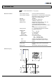
2 Interface Connection Making an EtherCAT interface cable For operating the BPG 402 gauge via EtherCAT, two interface cables conforming to the EtherCAT standard are required. If no such cables are available, make two according to the following indications. Cable type Ethernet Patch Cable or Crossover Cable (CAT5e quality) with FCC68 connector.
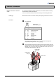
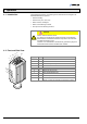
3 Operation 3.1 Introduction Via the EtherCAT interface, the following and further data are exchanged in the standardized EtherCAT protocol: • Pressure reading • Pressure unit (Torr, mbar, Pa) • Status and error messages • Status of the switching functions • Set Trip Point for switching functions Caution Caution: data transmission errors Any attempt to simultaneously operate the gauge via the RS232C Serial Interface and EtherCAT interface may result in incorrect data and data transmission errors.
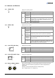
3.3 Indicators and Switches 3.3.1 LED Displays the operating status. RUN Color LED State off blinking Description INIT (initialization status) or no power applied to device. PREOP (pre-operational status). (200 ms on 200 ms off) green single flash (200 ms on 1000 ms off) on 3.3.2 LED SAFEOP (safe-operational status). Communication of cyclic data transfer running. Input values available, output values written to the device but not updated on device output. OP (operational status).
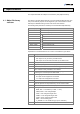
4 Object Structure This chapter describes the CANopen over EtherCAT (CoE) Object Dictionary. 4.1 Object Dictionary structure The objects in the CoE Object Dictionary can be accessed with SDO services, and many of the dictionary objects can be mapped for cyclic communication in PDOs. Each object is addressed using a 16-bit index and an 8-bit subindex. The following table presents the overall layout of the standard Object Dictionary. Index (hex.
4.2 Communication Profile Objects (0x1000…0x1FFF) Index The objects of the communication profile describe the basic EtherCAT properties of the BPG402 and are common to all EtherCAT slaves using the CoE communication protocol.
4.3 Manufacturer-specific Profile Objects (0x2000...0x5FFF) 4.3.1 Manufacturer Configuration Module 1 Subindex 0x02 4.3.2 Manufacturer Configuration Module 2 Subindex 0x02 The manufacturer-specific profile objects contain the manufacturer's model number and device configuration data, status and diagnostic data. The objects are described in the following tables.
Subindex 0x02 Indicates whether the Value parameter contains a value in over range. Reading Valid Module 1 Subindex 0x03 0 No Overrange Exceeded 1 Overrange Exceeded Indicates whether the Value parameter contains a value in under range. Reading Valid Module 1 4.4.
Subindex 0x03 Indicates whether the Value parameter contains a value in under range. Reading Valid Module 3 0 No Underrange Exceeded 1 Underrange Exceeded Subindex 0x05 Emission Status Off/On Module 4 0 OFF 1 ON Subindex 0x06 Degas Status Off/On Module 4 4.4.
4.5 Configuration Area (0x8000…0x8FFF) 4.5.
4.5.2 Configuration Trip Point 1 If "High Trip Source Index" is 0x800E1100 or 0x800F1100 the High Trip Point is equal with the value referenced in "High Trip Point Limit". The value defined in "High Trip Point Limit" is compared with the pressure value referenced by the "Source Index" parameter. If "Low Trip Source Index" is 0x800E1400 or 0x800F1400 the Low Trip Point is equal with the value referenced in "Low Trip Point Limit".
Subindex 0x04 Override Enable 0 1 Subindex 0x05 Override High Trip 0 1 Subindex 0x06 Disable Enable Disable Enable Override Low Trip 0 1 Disable Enable Subindex 0x11 High Trip Point Limit: High limit to trigger trip point condition if Input Value (I 0x900E, SI 0x01) is above this limit. Subindex 0x12 Object index of High Trip Point Value source.
4.5.3 Configuration Trip Point 2 Calculating the High Trip Point and Low Trip Point → 4.4.7.
Subindex 0x13 Percentage of Value referenced by High Trip Source Index in [%]. If High Trip Source Index is I 0x800F, SI 0x11 this parameter is not used. Subindex 0x14 Low Trip Point Limit: Low limit to trigger trip point condition if Input Value (I 0x900F, SI 0x01) is below this limit. Subindex 0x15 Object index of Low Trip Point Value source.
According to these definitions, 4 points are defined: 1 2 3 4 4.6.
4.6.2 4.6.3 Information Common Index SI DataType NV Access 9010 0x02 REAL x RO Highest Informational Measurement Value Module 2 0x03 REAL x RO Highest Precision Measurement Value Module 2 0x04 REAL x RO Lowest Precision Measurement Value Module 2 0x05 REAL x RO Lowest Informational Measurement Value Module 2 Subindex 0x02 Highest Informational Measurement Value: Highest value that the gauge can measure without a specified accuracy.
4.6.4 Information Trip Point 1/2 Index SI DataType NV Access PM Name 900E 0x01 REAL RO Input Value Trip Point 1 900F 0x01 REAL RO Input Value Trip Point 2 Subindex 0x01 (900E) Input Value Trip Point 1: Trip Point Input value as referenced by Source Index (I 0x800E, SI 0x0E). Subindex 0x01 (900F) Input Value Trip Point 2: 0 Trip Point Input value as referenced by Source Index (I 0x800F, SI 0x0E). 4.7 Device Area (0xF000...0xAFFF) 4.7.
4.7.5 Active Device Warning Details The "active device warning details" parameter describes the warning state of the complete device.
Subindex 0x03 Active Device Error Details Module 2 (Index F383) Bit 0 Subindex 0x01 4.7.
4.7.9 Device Warning Mask Index SI DataType NV Access F3A1 0x01 UDINT x RW Device Warning Mask Device 0x02 UDINT x RW Device Warning Mask Module 1 0x03 UDINT x RW Device Warning Mask Module 2 0x01 UDINT x RW Manufacturer Warning Mask F3A2 Subindex 0x01 Device Warning Mask Device: Mask bits for 0xF381:01 and 0xF391:01. Subindex 0x02 Device Warning Mask Module 1: Mask bits for 0xF381:02 and 0xF391:02.
Subindex 0x03 If the bit "Underrange” is set, all modules of the gauge are in an underrange condition. Subindex 0x11 The value copied from the measurement value of the active measuring module used for the Input PDO. Subindex 0x12 Identifies the module that is providing the measurement value, the latter of which is copied into the Active Value parameter for all Input PDO’s. 0 4.7.
Subindex 0x02 4.7.
Subindex 0x03 (F940) Access Rights (Index F940) 0 1 2 Subindex 0x04 (F940) 4.7.16 Command Degas ON / OFF User access to measurement and limited diagnostic features Service access to additional diagnostic features (vendor specific) Superuser access to vendor-specific parameters and features, e.g. calibration parameters, model number, serial numbers Software version of the basic device. Execution of this command will initiate or cancel a degas operation.
Subindex 0x01 An emission command is initiated when the following byte sequence is sent. Command Subindex 0x02 Byte 0 0: Emission OFF 1: Emission ON Byte 1 Index of the Sub Sensor module has to be 2 2: Hot Cathode Status (supported values) 0 1 2 3 255 Subindex 0x03 4.7.
Subindex 0x02 Status (supported values) 0 1 2 3 255 Subindex 0x03 4.7.19 Exception Reset Command Subindex 0x01 Reserved Reserved Last command completed, error, no response Reserved Command is executing Response Byte 0 See Subindex 0x02 Byte 1 Unused Execution of this command clears the latched exceptions.
Subindex 0x01 A device reset is initiated when the following byte sequence is sent. Command Byte 0 Byte 1 Byte 2 Byte 3 Subindex 0x02 Status (supported values) 0 1 2 3 255 Subindex 0x03 tira93e1 (2014-04) BPG402-SE.
Appendix A: 32 Literature [1] www.inficon.com Instruction Sheet BPG402-S, BPG402-SD, BPG402-SE, BPG402-SL, BPG402-SP tima46d1 (German) tima46e1 (English) INFICON AG, LI–9496 Balzers, Liechtenstein [2] www.inficon.com Instruction Sheet BPG402-SD, BPG402-SE, BPG402-SP tima47d1 (German) tima47e1 (English) INFICON AG, LI–9496 Balzers, Liechtenstein [3] www.inficon.
Notes tira93e1 (2014-04) BPG402-SE.
Original: English tira93e1 (2014-04) t i r a93e1 LI–9496 Balzers Liechtenstein Tel +423 / 388 3111 Fax +423 / 388 3700 reachus@inficon.com www.inficon.