Communication Protocol Profibus DP/V1 Interface for Bayard-Alpert Pirani Gauge BPG402-SP tira47e1 (2005-08) 1
About this Document This document describes the functionality and programming of the Profibus interface of the BPG402-SP gauge. For safety information on and technical data of the gauges, please refer to the respective operating manuals (→ [1], [3]). In information referring to the ionization vacuum measuring part of the gauge, the short designation "BA" (Bayard-Alpert measuring principle) is used. The designation "Pirani" is used in information referring to the Pirani vacuum measuring part of the gauge.
Contents tira47e1 (2005-08) BPG402SPv1.cp About this Document Product Identification Validity Intended Use Functional Principle Trademarks 2 2 2 2 2 2 1 General Data 1.1 Data Rate 1.2 Device Address 1.3 Ident Number 1.4 Configuration Data 1.5 User Parameter Data 1.6 Types of Communication 5 5 5 5 5 6 6 2 Data Exchange Mode 2.1 Acyclic Data Transmission with Profibus DPV1 Functionality 2.2 Structure of the Cyclic Data Telegrams in Data Exchange Mode 2.2.1 Parameter Channel 2.2.1.
3.2.3.2 Status ID 20 3.2.3.3 Data Type ID 21 3.2.3.4 Data Unit ID 22 3.2.3.5 Reading Valid ID 23 3.2.3.6 Full Scale ID 24 3.2.3.7 Safe State ID 39 3.2.3.8 Safe Value ID 40 3.2.3.9 Overrange ID 44 3.2.3.10 Underrange ID 45 3.2.4 Analog Sensor Input Function Block SLOT 1 / Instance 3, 4 3.2.4.1 Process Value ID 19 3.2.4.2 Status ID 20 3.2.4.3 Data Type ID 21 3.2.4.4 Data Unit ID 22 3.2.4.5 Reading Valid ID 23 3.3 Transducer Block 3.3.1 One Of N Vacuum Gauge Transducer Block / SLOT 1 3.3.1.
1 General Data 1.1 Data Rate The gauge supports all data rates defined in the EN 50170 standard (→ [5]) up to 12 Mbaud. Automatic data rate setting is supported. Alternatively, a fixed data rate can be selected. 1.2 Device Address The device address ( node address) must be set via two rotary switches when the gauge is installed. For unambiguous identification of the gauge in a Profibus environment, a node address is required. The node address setting is made on the gauge.
1.5 User Parameter Data Depending on the pressure unit setting ( data unit), the following configuration string has to be transmitted to the gauge (parameter data in hexadecimal format): Pressure unit User parameter data string COUNTS 1) 00 00 00 03 E9 Torr 00 00 00 05 15 Micron 00 00 00 05 16 mbar 00 00 00 05 1C Pascal 00 00 00 05 1D 1) 1.
2 Data Exchange Mode 2.1 Acyclic Data Transmission with Profibus DPV1 Functionality The reading and writing operations defined in Profibus are based on a slot index address scheme.
2.2 Structure of the Cyclic Data Telegrams in Data Exchange Mode In Data Exchange mode, the DP master class 1 cyclically transmits data from and to all slaves that are connected to the bus. In this document, data transmitted from the slave to the master are called "input data" and data transmitted from the master to the slave are called "output data".
2.2.1.1 PKE Parameter Signature Value The instruction and response are represented in the first two bytes (PKE) of the parameter channel: 15 14 13 12 11 10 AK Where: Bit position 9 8 7 6 5 res. 4 3 2 1 0 Slot Bits Meaning 15 … 12 AK Instruction/response signature 11 … 8 Reserved 7 … 0 Define the slot from which data are read or onto which a value is to be written Instruction signature In Master ⇒ Slave communication, the AK field contains the instruction signature of the master.
2.2.1.3 Error Code (Error Message) In the event of a transmission error (AK response signature = 7), the slave transmits an error code in byte positions 7 and 8 (data type: INT16).
2.3 Cyclic Message Telegrams The message telegrams listed below are implemented in the gauge. They can be selected according to requirements. When selecting a message telegram, ascertain what output format of the measured value (integer/float) is required and whether a parameter channel is needed or not. The gauge can also be operated in such a way that the master does not transmit any output data to the slave.
3 Block Model Data to the BPG402-SP can be transmitted by means of a number of communication protocols and corresponding masters. Profibus defines a master class 1 as normal control unit of the slave (typically a PLC) and a master class 2 as configuration and service unit. The following communication protocols are defined according to the Profibus DPV1 standard.
3.1 Device Block tira47e1 (2005-08) BPG402SPv1.cp The following table lists the services and parameters integrated in the Device Block (→ Appendix A for abbreviations).
3.1.1 Information on the Individual Indices 3.1.1.1 Block Type ID 16 The Block Type Parameter contains an ID which describes the block type. The block type ID of the Device Block 1. The other defined block types are listed in Appendix B. 3.1.1.2 Device Type ID 17 The Device Type identifies the device type which is connected to the field bus via Profibus. The Device Type of the BPG402-SP gauge is "CG", the abbreviation of Combination Gauge. 3.1.1.
3.1.1.10 Exception Status ID 26 The Exception Status describes the alarm and warning states of the gauge in an "Expanded error output format". A difference is made between warnings and errors. Alarms and errors are divided into three groups (→ sections "Exception Detail Alarm" and "Exception Detail Warning" for details): • ALARM / Warning Device Common • ALARM / Warning Device Specific • ALARM / Warning Manufacturer Specific For errors that occur independently of the type of device used, e.g.
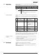
3.1.1.11 Exception Detail Alarm ID 27 If, in the Exception Status, one of the bits 0 … 2 is set, the current error can be read in the "Exception Detail Alarm" parameter. The "Exception Detail Alarm" parameter consists of a total of 10 bytes that inform on the error status of the gauge.
Device Exception Detail Alarm Bit Device Exception Detail 0 Referring to Pirani tira47e1 (2005-08) BPG402SPv1.cp Device Exception Detail 1 Referring to Pirani 0 0 0 0 1 0 1 Electronics / sensor error 2 0 2 0 3 0 3 0 4 0 4 0 5 0 5 0 6 0 6 0 7 0 7 0 This byte is a copy of Sensor Alarm byte 0 of Pirani Transducer Block. This byte is a copy of Sensor Alarm byte 1 of Pirani Transducer Block.
3.1.1.12 Exception Detail Warning ID 28 If, in the Exception Status, one of bits 4 … 6 is set, the current warning can be read in the parameter "Exception Detail Warning". The Exception Detail Warning parameter consists of a total of 11 bytes that inform on the error status of the gauge.
Common Exception Detail Warning Bit 0 Common Exception Detail 0 0 Bit 0 Common Exception Detail 1 0 1 0 1 0 2 EPROM exception 2 0 3 EEPROM exception 3 0 4 RAM exception 4 0 5 0 5 0 6 0 6 0 7 0 7 0 The warning bits are set in the same way as the error bits because here, warnings have the same meaning as errors.
Manufacturer Exception Detail Warning 0 Manufacturer Exception Detail 0 is set to "1", if there is an internal communication error in the gauge. The following parameters are copies of the ID 27 and ID 28. They are used only if you want to access these parameters by the parameter channel. 3.1.1.13 Copy Common Exception Detail Alarm 0 ID 204 This parameter corresponds to the Common Exception Detail Alarm of the Exception Detail Alarm (ID 27). 3.1.1.
3.1.2 Device Block, Device Behavior The BPG402-SP behaves as described in the status diagram below. (0) NORMAL (13) (13 ) 3) (1 (14) INIT RUNNING (10) IDLE (4) (5) ABORT (8) (3) SELFTEST EXCEPTION OK ) (1 (2) SELFTESTING EXECUTING (9) CRITICAL FAULT After the start, the gauge independently runs through the INIT and SELFTESTING status and eventually changes to the IDLE status (if there is no error) or to the SELFTEST_EXCEPTION status (if there is a gauge error).
Device statuses 3.1.2.1 Device Block State Command Status name Description NORMAL The communication interface can respond to commands. All defined blocks of the gauge exist. RUNNING All block instances are initialized and the individual parameters have their initial or default values. SELFTESTING In this status, the gauge performs a selftest. IDLE All blocks defined in the gauge are initialized and the complete hardware has been tested and found free of errors.
3.2 Analog Input Block All gauge functions of the BPG402-SP are described in the Analog Input Block. Since the gauge includes two measuring systems, there are also two Analog Input Block Instances representing the Pirani and the ionization measuring part (BA) respectively. 3.2.
3.2.2 Analog Sensor Input Function Block SLOT 1 / Instance 1 3.2.2.1 Process Value ID 19 Instance 1 of the Analog Sensor Input Function Blocks describes the functionality of the Pirani measuring part of the gauge.
Coding 3.2.2.4 Data Unit ID 22 Data type 3 Integer16 8 Float (default) The gauge supports the following pressure units: Coding (dec) Data type 1001 COUNTS 1301 Torr 1302 mTorr (Micron) 1308 mbar 1309 Pascal For safety reasons, it is not possible to change the pressure unit while the gauge is cyclically interchanging data with a DP/V0 master. The data unit setting can only be modified when the gauge is in the IDLE status.
3.2.2.7 Safe State ID 39 When the gauge is not in the EXECUTING status (ID 25, Device Block) or if there is a device error, a value defined by Safe State is output as pressure value: Safe State Coding PV behavior Zero 0 The Process Value (measured value ID 19) is set to 0. Full Scale 1 The Process Value (measured value ID 19) is set to the full scale value (ID 24). Hold Last Value 2 The Process Value is set to the last valid value obtained in the EXECUTING status.
3.2.3 Analog Sensor Input Function Block SLOT 1 / Instance 2 3.2.3.1 Process Value ID 19 Instance 2 of the Analog Sensor Input Function Block describes the functionality of the BA measuring part of the gauge.
If the data type is set in one instance, that data type setting applies to all instances. Likewise, when a standard telegram is selected, the data type used by that standard telegram will be valid for all instances. 3.2.3.
3.2.3.7 Safe State ID 39 When the gauge is not in the EXECUTING state (ID 25, Device Block) or if there is a device error, a value defined by Safe State is output as pressure value: Safe State Coding PV behavior Zero 0 The Process Value (measured value ID 19) is set to 0. Full Scale 1 The Process Value (measured value ID 19) is set to the full scale value (ID 24). Hold Last Value 2 The Process Value is set to the last valid value obtained in the EXECUTING status.
3.2.4 Analog Sensor Input Function Block SLOT 1 / Instance 3, 4 3.2.4.1 Process Value ID 19 Instance 3 and 4 of the Analog Sensor Input Function Block describe the functionality of the threshold potentiometers used to set the gauges switching functions ("Setpoint A and B, → [3]).
3.2.4.4 Data Unit ID 22 The gauge supports the following pressure units: Coding (dec) Pressure unit 1001 COUNTS 1301 Torr 1302 mTorr (Micron) 1308 mbar 1309 Pascal For safety reasons, it is not possible to change the pressure unit while the gauge is cyclically interchanging data with a DP/V0 master. The data unit setting can only be modified when the gauge is in the IDLE status. In cyclic data traffic, the data unit must be set in the User Parameter Data.
3.3 Transducer Block 3.3.1 One Of N Vacuum Gauge Transducer Block / SLOT 1 3.3.1.1 One Of N Status Extension ID 120 Name Structure Data type One Of N Status Extension Simple Bytes Access Store UINT8 1 1/2_R V This parameter indicates whether the overrange or underrange of the gauge is exceeded.
3.3.2.4 Sensor Warning ID 104 This parameter indicates the detectable warnings occurring in connection with the Pirani measuring part. Bit 7 Bit 6 Bit 5 Bit 4 Bit 3 Bit 2 Bit 1 Bit 0 Byte 0 0 0 0 0 0 0 0 0 Byte 1 0 0 0 0 0 0 Electronics Warning 0 The Sensor Warning bits defined here are copied into the Device Block ID 28 in the "Device Exception Detail Warning" range of the Pirani measuring part. 3.3.
3.3.3.3 Sensor Alarm ID 103 This parameter indicates the detectable errors occurring in connection with the BA measuring part. Bit7 Bit6 Bit5 Bit4 Bit3 Bit2 Byte 0 0 0 0 0 0 0 Byte 1 0 0 0 0 0 0 Bit 1 Bit 0 Sensor Filament 2 Sensor Filament 1 Alarm 1) Alarm 1) Electronics Failure 2) 1) Meaning → below, table Filament status. 2) Electronics Failure includes a sensor error.
3.3.3.6 Emission Current ID 106 This parameter indicates the value of the emission current in mA. Emission currents [mA] 0 0.025 5 20 3.3.3.7 Active Filament ID 108 3.3.3.8 Degas Status ID 109 The Parameter defines / indicates the active filament (→ Mode Filament Selection). Active Filament Byte value 1 1 filament 1 active Meaning 2 2 filament 2 active This parameter indicates whether the gauge is in Degas mode. Degas Status Meaning FALSE Degas Off TRUE Degas On 3.3.3.
3.3.3.12 Hot Cathode Block State Command ID 14 This service is used for activating degas and emission modes via Profibus.
Appendix A: Definitions Data types Abbreviation 7 -2 … (2 - 1) Integer 1 byte INT16 -215 … (215 - 1) Integer 2 byte 31 Data access tira47e1 (2005-08) BPG402SPv1.cp 31 INT32 -2 UINT8 0 … (28 - 1) … (2 - 1) Integer 4 byte Unsigned integer 1 byte 0 … (2 16 - 1) Unsigned integer 2 byte UINT32 0 … (2 32 - 1) Unsigned integer 4 byte FLOAT ±3.
Excerpts from: "PROFIBUS Profile for SEMI" (→ [4], [6], [7]) 38 The following table explains terms used in connection with the Profibus. Term Meaning Alert Elements Alert Elements are used to communicate notification messages from slave to master when warnings, alarms or events are detected. Application A software functional unit consisting of an interconnected aggregation of function blocks, events and objects, which may be distributed and which may have interfaces with other applications.
Excerpts from: "PROFIBUS Profile for SEMI" (cont.) tira47e1 (2005-08) BPG402SPv1.cp Term Meaning Function Block Application Application of an automation system performed by a Device Block, Function Block, Transducer Block and accompanied elements. Instance A set of data related to an invocation of a function block or a class. Internal Resolution (ir) The internal resolution is 16383 (3FFFhex) for 100% and -16384 (C000hex) for -100% of the range.
Appendix B: Block Type Currently defined Block Type IDs Block Name Block Type ID Device Block 1 Sensor Analog Input Function Block 2 One of N Channel Sensor Analog Input Function Block 3 Multi Channel Sensor Analog Input Function Block 4 Discrete Input Function Block 5 Actuation Analog Output Function Block 6 Discrete Output Function Block 7 Analog Output Function Block 8 Single Stage Controller Function Block 9 Gas Calibration Transducer Block 10 Flow Transducer Block 11 Sensor Ana
Appendix C: Electrical Connections Technical data of BPG402 gauges → Sensor cable connection [1], [2], [3]. ( Thresholdvalues ) 1) SP A SP B 3 6 4 SP A 1 11 9 SP B 13 14 Degas 7 - Measuring signal Degas 2 - 12 + 1.25 AT Ub 42 kΩ 8 10 Ident.
Profibus connection 1 5 D-Sub, 9 pins, male soldering side 6 Pin 1 Pin 2 Pin 3 Pin 4 Pin 5 Pin 6 Pin 7 Pin 8 Pin 9 42 9 not connected not connected RxD/TxD-P CNTR-P DGND VP not connected RxD/TxD-N not connected 1) 2) 2) 1) Only to be connected if an optical link module is used. 2) Only required as line termination for devices at both ends of bus cable [4]). (→ tira47e1 (2005-08) BPG402SPv1.
Appendix D: Literature tira47e1 (2005-08) BPG402SPv1.cp [1] www.inficon.com Instruction Sheet Bayard-Alpert Pirani Gauge BPG402, BPG402-SD, BPG402-SP tima46e1 INFICON AG, LI–9496 Balzers, Liechtenstein [2] www.inficon.com Instruction Sheet Bayard-Alpert Pirani Gauge BPG402-SD, BPG402-SP tima47e1 INFICON AG, LI–9496 Balzers, Liechtenstein [3] www.inficon.com Operating Manual Bayard-Alpert Pirani Gauge BPG402, BPG402-SD, BPG402-SP tina46e1 INFICON AG, LI–9496 Balzers, Liechtenstein [4] www.
Original: German tira47d1 (2005-08) t i r a47e1 LI–9496 Balzers Liechtenstein Tel +423 / 388 3111 Fax +423 / 388 3700 reachus@inficon.com www.inficon.