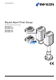
Operating Manual Bayard-Alpert Pirani Gauge Dual Filament Bayard-Alpert Pirani Gauge BPG402-S BPG402-SD BPG402-SL BPG402-SP tina46e1-a (2010-03) 1
Product Identification In all communications with INFICON, please specify the information on the product nameplate. For convenient reference copy that information into the space provided below.
Functional Principle tina46e1-a (2010-03) BPG402.om Over the whole measuring range, the gauge has a continuous characteristic curve and its measuring signal is output as logarithm of the pressure. The gauge functions with a Bayard-Alpert hot cathode ionization measurement system (for p < 2.0×10⁻² mbar) and a Pirani measurement system (for p > 5.5×10⁻³ mbar). In the overlapping pressure range of 2.0×10⁻² … 5.5×10⁻³ mbar, a mixed signal of the two measurement systems is output.
Contents 4 Product Identification Validity Intended Use Functional Principle 2 2 2 3 1 Safety 1.1 Symbols Used 1.2 Personnel Qualifications 1.3 General Safety Instructions 1.4 Liability and Warranty 6 6 6 7 7 2 Technical Data 8 3 Installation 3.1 Vacuum Connection 3.1.1 Removing and Installing the Electronics Unit 3.1.2 Using the Optional Baffle 3.2 Electrical Connection 3.2.1 Use With INFICON VGC40x Vacuum Gauge Controller 3.2.2 Use With Other Controllers 3.2.2.
7 Options 45 8 Spare Parts 45 9 Storage 45 10 Returning the Product 46 11 Disposal 46 Appendix A: Relationship Output Signal – Pressure B: Gas Type Dependence C: Literature 47 47 48 50 Declaration of Contamination 51 For cross-references within this document, the symbol (→ XY) is used, for crossreferences to further documents and data sources, the symbol (→ [Z]). tina46e1-a (2010-03) BPG402.
1 Safety 1.1 Symbols Used DANGER Information on preventing any kind of physical injury. WARNING Information on preventing extensive equipment and environmental damage. Caution Information on correct handling or use. Disregard can lead to malfunctions or minor equipment damage. Notice Hint, recommendation The result is O.K. The result is not as expected Optical inspection Waiting time, reaction time 1.
1.3 General Safety Instructions • Adhere to the applicable regulations and take the necessary precautions for the process media used. Consider possible reactions between the materials (→ 11) and the process media. Consider possible reactions of the process media (e.g. explosion) due to the heat generated by the product. • Adhere to the applicable regulations and take the necessary precautions for all work you are going to do and consider the safety instructions in this document.
2 Technical Data Measurement Emission Measurement range (air, O2, CO, N2) Accuracy (after 10 min. stabilization) Repeatability (after 10 min. stabilization) 5×10⁻¹⁰ … 1000 mbar, continuous 15% of reading in the range of 1×10⁻⁸ … 10-2 mbar 5% of reading in the range of 1×10⁻⁸ … 10-2 mbar Gas type dependence → Appendix B Switching on threshold Switching off threshold Emission current -6 p ≤7.2×10 mbar -6 7.2×10 mbar < p < 3.
Switching functions BPG402-S, -SL BPG402-SD, -SP Adjustment range Hysteresis Relaiskontaktbelastung RS232C interface Data rate Data format Connections (sensor cable connector) TxD (Transmit Data) RxD (Receive Data) GND 1 ("SETPOINT") 2 ("SETPOINT A, B") -9 1×10 mbar … 100 mbar Setpoints adjustable via potentiometers, one floating, normally open relay contact per setpoint (→ 19, 20, 37). (Adjusting the setpoints via field bus → corresponding bus section) 10% of the threshold value ≤30 VDC, ≤0.
Profibus interface (BPG402-SP) Fieldbus name Standard applied Profibus → Interface, physical Data rate ≤12 MBaud (→ Node address Local (Adjustable via hexadecimal "ADDRESS", "MSD", "LSD" switches) Default setting Via Profibus ("ADDRESS" switches set to >7Dhex (>125dec)) 00 … 7Dhex (0 … 125dec) 5Chex Profibus connection Cable Cable length, system wiring Display (BPG402-S only) [7] → [2], [7] RS485 Communication protocol, data format Display panel Dimensions Pressure units Selecting the pressure u
Electrical connection For reasons of compatibility, the expression "sensor cable" is used for all BPG402 versions in this document, although the pressure reading of the gauges with fieldbus interface (BPG402-SD and BPG402-SP) is normally transmitted via the corresponding bus.
Dimensions [mm] 4-40UNC 2B 4-40UNC 2B DN 25 ISO-KF DN 40 CF-R 4-40UNC 2B Gauges with DeviceNet connector are 14 mm longer. DN 40 CF-R Weight 12 353-570, 353-572 353-571, 353-573 353-578 ≈450 g ≈710 g ≈917 g 353-574, 353-576 353-575, 353-577 ≈490 g ≈750 g tina46e1-a (2010-03) BPG402.
3 Installation 3.1 Vacuum Connection DANGER DANGER: overpressure in the vacuum system >1 bar Injury caused by released parts and harm caused by escaping process gases can result if clamps are opened while the vacuum system is pressurized. Do not open any clamps while the vacuum system is pressurized. Use the type of clamps which are suited to overpressure. DANGER The gauge must be electrically connected to the grounded vacuum chamber.
Procedure Remove the protective lid and install the gauge to the vacuum system. Seal with centering ring Protective lid (keep it) Clamp 3.1.1 Removing and Installing the Electronics Unit Required tools / material • Allen wrench, AF 2.5 Removing the electronics unit Unscrew the hexagon socket set screw (1) on the side of the electronics unit (2). 2 1 Remove the electronics unit without twisting it. 14 tina46e1-a (2010-03) BPG402.
Installing the electronics unit Place the electronics unit (2) on the sensor (3) (be careful to correctly align the pins and notch (4)). 4 2 3 Slide the electronics unit in to the mechanical stop and lock it with the hexagon socket set screw. 3.1.2 Using the Optional Baffle In severely contaminating processes and to protect measurement electrodes optically against light and fast charged particles, replacement of the built-in grid by the optional baffle (→ 45) is recommended.
Carefully place the baffle onto the sensor opening. Using a pin, press the baffle down in the center until it catches. Deinstallation 16 Carefully remove the baffle with the screwdriver. tina46e1-a (2010-03) BPG402.
3.2 Electrical Connection 3.2.1 Use With INFICON VGC40x Vacuum Gauge Controller If the gauge is used with an INFICON VGC40x controller, a corresponding sensor cable is required (→ [3]). The sensor cable permits supplying the gauge with power, transmitting measurement values and gauge statuses, and making parameter settings.
3.2.2.1 Making an Individual Sensor Cable Cable type For reasons of compatibility, the expression "sensor cable" is used for all BPG402 versions in this document, although the pressure reading of the gauges with fieldbus interface (BPG402-SD or BPG402-SP) is normally transmitted via DeviceNet or Profibus. The sensor cable is required for supplying all BPG402 types with power. It also permits access to the relay contacts of the switching functions (→ 19, 20).
Sensor cable connection BPG402-S, -SL ( ) 1) 3 Threshold value, SP 4 SP 1 11 Filament status 9 13 TxD RS232 RxD 14 Degas 7 Degas 6 2 Measuring signal - 12 1.25 AT VS 42 kΩ 8 10 Ident. 5 15 Common (power GND 24V supply) Ground (housing, vacuum connection) 9 1 15 8 - - 24V D-Sub,15 pins, female, soldering side Electrical connection Pin 1 Pin 2 Pin 3 Pin 4 Pin 5 Pin 6 Pin 7 Pin 8 Pin 9 Pin 10 Pin 11 Pin 12 Pin 13 Pin 14 Pin 15 tina46e1-a (2010-03) BPG402.
Sensor cable connection BPG402-SD, -SP ( ) 1) SP A Threshold value SP B 3 6 4 SP A 1 11 SP B 9 13 TxD RS232 RxD 14 Degas 7 Degas 6 2 Measuring signal - 12 1.25 AT VS 42 kΩ 8 10 Ident.
For cable lengths up to 5 m (0.34 mm2 conductor cross-section) the output signal can be measured directly between the positive signal output (Pin 2) and supply common (Pin 5). At greater cable lengths, differential measurement between signal output (Pin 2) and signal common (Pin 12) is recommended. Reassemble the cable connector. On the other cable end, terminate the cable according to the requirements of the gauge controller you are using.
Plug the DeviceNet (and sensor) cable connector into the gauge. DeviceNet cable Sensor cable Lock the DeviceNet (and sensor) cable connector. 3.2.2.3 Making a Profibus Interface Cable (BPG402-SP) Cable type For operating BPG402-SP via Profibus, an interface cable conforming to the Profibus standard is required. If no such cable is available, make one according to the following indications. Only a cable that is suited to Profibus operation may be used (→ [5], [7]).
Plug the Profibus (and sensor) cable connector into the gauge. Sensor cable Profibus cable Lock the Profibus cable (and sensor cable) connector. 3.2.3 Using the Optional Power Supply (With RS232C Line) Technical data The optional 24 VDC power supply (→ 45) allows RS232C operation of the BPG402-Sx gauge with any suitable instrument or control device. The instrument or control device needs to be equipped with a software that supports the RS232C protocol of the gauge (→ 30).
Connecting the power supply Connect the power supply to the gauge and lock the connector with the screws. Connect the RS232C line to the instrument or control device and lock the connector with the screws. PC RS232C Power supply Mains BPG402-Sx Connect the power supply to the mains. 24 tina46e1-a (2010-03) BPG402.
4 Operation 4.1 Measuring Principle, Measuring Behavior Bayard-Alpert The BPG402-Sx vacuum gauges consist of two separate measuring systems (hot cathode Bayard-Alpert (BA) and Pirani). The hot cathode measuring system uses an electrode system according to BayardAlpert which is designed for a low X-ray limit. The measuring principle of this measuring system is based on gas ionization.
Schematic VB Pirani sensor The bridge voltage VB is a measure for the gas pressure and is further processed electronically (linearization, conversion). Measuring range The BPG402 -Sx gauges continuously cover the measuring range 5×10⁻¹⁰ mbar … 1000 mbar. • The Pirani constantly monitors the pressure. • The hot cathode (controlled by the Pirani) is activated only at pressures <2.4×10⁻² mbar.
4.2 Operational Principle of the Gauge The analog measuring signals of the Bayard-Alpert and Pirani sensors are converted into a digital form by a micro-controller and subsequently converted to a value representing the measured total pressure. After further processing this value is available as analog measurement signal (0 … +10 V) at the output (sensor cable connector Pin 2 and Pin 12). The maximum output signal is internally limited to +10 V (atmosphere).
4.5 Filament Status 4.5.1 Filament Status Indicator The status of the dual filament hot cathode is indicated by a LED on top of the gauge. Filament status indicator LED Filament status Emission Filament status indicator off on on on dark green green, flashing red – Both filaments O.K. One filament broken Both filaments broken INFICON recommends the replacement of the sensor as soon as the first filament failure has been detected (replacing the sensor → 44). 4.5.
4.7 Emission Control Mode General The emission control mode function defines the rules by which the emission of the gauge is switched on and off. The manual mode feature has a positive effect on gauge live time, mainly in process situations where the process chamber has to be vented frequently. Emission Control Mode Description • Automatic (AUTO) By default, the automatic mode is active and the emission is switched on and off automatically by the gauge.
Error Display No error (green background illumination) Pirani sensor error (red background illumination) Bayard-Alpert sensor error (red background illumination) EEPROM error (red background illumination) Internal data communication failure (red background illumination) What to do in case of problems → 4.9 RS232C Interface 42. The built-in RS232C interface (all BPG402 versions) allows transmission of digital measurement data and instrument conditions as well as the setting of instrument parameters.
Electrical connections 4.9.1.1 Output String (Transmit) Format of the output string • TxD Pin 13 • RxD Pin 14 • Pin 5 GND (Sensor cable connector) The complete output string (frame) is nine bytes (byte 0 … 8). The data string is seven bytes (byte 1 … 7).
Error byte Software version Bit 7 Bit 3 Bit 1 Bit 0 Definition x x x x not used Bit 6 Bit 5 Bit 4 Bit 2 Definition x x x 1 x x 1 x x 1 x x 1 x x x 2) Both filaments broken 3) One filament broken Pirani error 2) hot cathode error 3) hot cathode warning electronics error / EEPROM error The software version of the gauge can be calculated from the value of byte 6 of the transmitted string according to the following rule: Version No = ValueByte 6 / 20 (Example: According to the above fo
4.9.1.2 Input String (Receive) Format of the input string For transmission of the commands to the gauge, a string (frame) of five bytes is sent (without ). Byte 1 … 3 form the data string. Byte no 0 1 2 3 4 4) Admissible input strings Function Length of data string Data Data Data Check sum (from bytes No 1 … 3) Value 3 0 … 255 Comment set value → admissible input strings → admissible input strings → admissible input strings (low byte of sum) High order bytes are ignored in the check sum.
4.10 DeviceNet Interface (BPG402-SD) This interface allows operation of BPG402-SD with part number 353-576 and 353-577 in connection with other devices that are suited for DeviceNet operation. The physical interface and communication firmware of BPG402-SD comply with the DeviceNet standard (→ [4], [6]). Two adjustable switching functions are integrated in BPG402-SD. The corresponding relay contacts are available at the sensor cable connector (→ 8, 20, 37).
4.10.2.3 Data Rate Setting The admissible data rate depends on a number of factors such as system parameters and cable length (→ [4], [6]). It can be set on the gauge or programmed via DeviceNet. By means of the "RATE" switch, the data rate can be set to 125 ("1"), 250 ("2") or 500 kBaud ("5"). Default data rate setting is 500 kBaud. If the switch is in any of the "P" positions, the data rate is programmable via DeviceNet (→ [1]). 4.10.
4.11 Profibus Interface (BPG402-SP) This interface allows operation of BPG402-SP with part number 353-574 and 353-575 in connection with other devices that are suited for Profibus operation. The physical interface and communication firmware of BPG402-SP comply with the Profibus standard (→ [5], [7]. Two adjustable switching functions are integrated in the BPG402-SP. The corresponding relay contacts are available at the sensor cable connector (→ 8, 20, 37).
4.12 Switching Functions The BPG402-S, SL have one, the gauges BPG402-SD and BPG402-SP have two independent, manually adjustable switching functions. Each switching function has a floating, normally open relay contact. The relay contacts are accessible at the sensor cable connector (→ 19, 20). The threshold values of the switching functions can be set within the pressure range 1×10⁻⁹ mbar … 100 mbar via potentiometers "SETPOINT" (BPG402-S, SL) or "SETPOINT A" and "SETPOINT B" (BPG402-SD, SP).
4.12.1 Setting the Switching Functions Required tools Procedure The threshold values of the switching functions are set locally on the potentiometers of the gauge that are accessible via the openings on one side of the gauge housing. • Voltmeter • Ohmmeter or continuity checker • Screwdriver, max. ø2.5 mm The procedure for setting thresholds is identical for all switching functions. Put the gauge into operation.
5 Deinstallation DANGER DANGER: contaminated parts Contaminated parts can be detrimental to health and environment. Before beginning to work, find out whether any parts are contaminated. Adhere to the relevant regulations and take the necessary precautions when handling contaminated parts. Caution Caution: vacuum component Dirt and damages impair the function of the vacuum component. When handling vacuum components, take appropriate measures to ensure cleanliness and prevent damages.
Remove gauge from the vacuum system and replace the protective lid. Protective lid 40 tina46e1-a (2010-03) BPG402.
6 Maintenance, Repair DANGER DANGER: contaminated parts Contaminated parts can be detrimental to health and environment. Before beginning to work, find out whether any parts are contaminated. Adhere to the relevant regulations and take the necessary precautions when handling contaminated parts. 6.1 Cleaning the Gauge Small deposits on the electrode system can be removed by baking the anode (Degas → 27). In the case of severe contamination, the baffle can be exchanged easily (→ 15).
Insert the pin through the opening shown in the following illustration and push the button inside for 1 s. BPG402-S BPG402-SL BPG402-SD BPG402-SP max. ø1.3 Gauges with display will show the reading "1000 mbar". 6.2.2 Zero Point Adjustment Zero point readjustments are automatically carried out during operation of the gauge, no manual adjustment is needed. 6.3 What to Do in Case of Problems In the event of a fault or a complete failure of the output signal, the gauge can easily be checked.
Problem Possible cause Correction Output signal permanently ≈0V Sensor cable defective or not correctly connected Check the sensor cable No supply voltage Turn on the power supply Gauge in an undefined status Turn the gauge off and on again (reset) Output signal ≈+0.1 V (Display: "FAIL EL") EEPROM failure Turn the gauge off and on again after 5 s Replace the electronics unit Output signal ≈+0.
View on sensor pins 7 8 6 1 5 9 2 4 3 6 7 8 2 4 5 3 1 9 Hot cathode (FIL 1) ca. 0.15 Ohm Hot cathode (FIL 2) ca. 0.15 Ohm Pirani sensor 1 Pirani sensor 2 ca. 37 Ohm ca. 37 Ohm GND (connected to sensor housing) Ion collector Correction All of the above faults can only be remedied by replacing the sensor (→ Troubleshooting on Fieldbus gauges (BPG402-SD, -SP) Error diagnosis of fieldbus gauges can only be performed as described above for the basic sensor and sensor electronics.
7 Options Ordering number 24 VDC power supply / RS232C line (→ Baffle DN 25 ISO-KF / DN 40 CF-R (→ 23) 15) 353-511 353-512 8 Spare Parts When ordering spare parts, always indicate: • All information on the product nameplate • Description and part number Ordering number BPG402-S, -SD, -SP Replacement sensor, DN 25 ISO-KF (including allen wrench) Replacement sensor, DN 40 CF-R (including allen wrench) 354-494 354-495 Ordering number BPG402-SL Replacement sensor, DN 40 CF-R, long tube (including alle
10 Returning the Product WARNING WARNING: forwarding contaminated products Contaminated products (e.g. radioactive, toxic, caustic or biological hazard) can be detrimental to health and environment. Products returned to INFICON should preferably be free of harmful substances. Adhere to the forwarding regulations of all involved countries and forwarding companies and enclose a duly completed declaration of contamination (→ 51).
Appendix A: Relationship Output Signal – Pressure p = 10(U - 7.75) / 0.75 + c Conversion formulae U = 0.75 × (log p - c) + 7.75 where Conversion curve U p c [V] [V] [V] [mbar] [Pa] [Torr] 0 2 -0.125 Pressure p [mbar] 1E+04 1E+03 1E+02 1E+01 1E+00 1E–04 1E–05 inadm issible range 1E–03 sensor error 1E–02 inadm issible range 1E–01 1E–06 1E–07 1E–08 1E–09 1E–10 0.0 1.0 2.0 3.0 4.0 5.0 6.0 7.0 8.0 9.0 10.0 Measuring signal U [V] Conversion table Output signal U [V] [mbar] 0.
B: Gas Type Dependence Indication range above 10-2 mbar Pressure indicated (gauge adjusted for air, Pirani-only mode) p (mbar) 102 H2 He Ne 8 6 4 2 101 Indication range above 10-2 mbar 8 6 4 Air O2 CO N2 CO2 Ar Freon 12 Kr 2 Xe 100 8 6 4 2 10–1 8 6 4 2 10–2 H2O vapor 8 6 4 2 10–3 10–3 2 4 6 10–2 2 4 6 10–1 2 4 6 100 2 4 6 101 2 4 6 102 peff (mbar) Calibration in pressure range 10-2 … 1 mbar The gas type dependence in the pressure range 10-2 … 1 mbar (Pirani pressure range)
Calibration in pressure range <10-3 mbar The gas type dependence in the pressure range <10-3 mbar can be compensated by means of the following formula (gauge adjusted for air): peff = C × indicated pressure where Gas type Calibration factor C Air, O2, CO, N2 N2 He Ne H2 Ar Kr Xe 1.0 1.0 5.9 4.1 2.4 0.8 0.5 0.4 (The above calibration factors are mean values.) A mixture of gases and vapors is often involved.
C: 50 Literature [1] www.inficon.com Communication Protocol DeviceNet™ BPG402-SD tira46e1 (English) INFICON AG, LI–9496 Balzers, Liechtenstein [2] www.inficon.com Communication Protocol Profibus BPG402-SP tira47d1 (German) tira47e1 (English) INFICON AG, LI–9496 Balzers, Liechtenstein [3] www.inficon.com Product descriptions and downloads INFICON AG, LI–9496 Balzers, Liechtenstein [4] www.odva.org Open DeviceNet Vendor Association, Inc. DeviceNet™ Specifications [5] www.profibus.
Declaration of Contamination The service, repair, and/or disposal of vacuum equipment and components will only be carried out if a correctly completed declaration has been submitted. Non-completion will result in delay. This declaration may only be completed (in block letters) and signed by authorized and qualified staff. Description of product Reason for return Type Part number Serial number Operating fluid(s) used (Must be drained before shipping.
Original: German tina46d1-a (2010-03) t i na46e1- a LI–9496 Balzers Liechtenstein Tel +423 / 388 3111 Fax +423 / 388 3700 reachus@inficon.com www.inficon.