
Manual

Bayard-Alpert Pirani Gauge
Dual Filament Bayard-Alpert Pirani Gauge
BPG402-S
BPG402-SD
BPG402-SL
BPG402-SP
Instruction Sheet
Incl. EC Declaration of Conformity
tima46e1-b (2010-03)
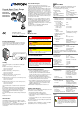
Product Identification
In all communications with INFICON, please specify the in-
formation given on the product nameplate. For convenient
reference copy that information into the space provided
below.
Model:
PN:
SN:
V W
INFICON AG, LI-9496 Balzers
Validity
This document applies to products with the following part
numbers:
BPG402-S
(without display, 1 switching function)
353-570
(DN 25 ISO-KF)
353-571
(DN 40 CF-R)
BPG402-S
(with display, 1 switching function)
353-572
(DN 25 ISO-KF)
353-573
(DN 40 CF-R)
BPG402-SL
(without display, 1 switching function)
353-578
(DN 40 CF-R, long tube)
BPG402-SD
(with DeviceNet interface and 2 switching functions)
353-576
(DN 25 ISO-KF)
353-577
(DN 40 CF-R)
BPG402-SP
(with Profibus interface and 2 switching functions)
353-574
(DN 25 ISO-KF)
353-575
(DN 40 CF-R)
The part number (PN) can be taken from the product name
plate.
If not indicated otherwise in the legends, the illustrations in
this document correspond to the gauge with part number
353-572. They apply to the other gauges by analogy (more
detailed information on BPG402-SD and -SP gauges
→ [1] and [2]).
We reserve the right to make technical changes without prior
notice.
All dimensions in mm.
Intended Use
The BPG402-Sx gauges have been designed for vacuum
measurement of non-flammable gases and gas mixtures in a
pressure range 5×10
-10
… 1000 mbar.
The gauges can be operated in connection with the VGC 40x
Vacuum Gauge Controller or with another instrument or
control device.
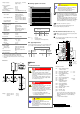
Functional Principle
Over the whole measuring range, the gauge has a
continuous characteristic curve and its measuring signal is
output as logarithm of the pressure.
The gauge functions with a Bayard-Alpert hot cathode ioni-
zation measurement system (for p < 2.0×10
-2
mbar) and a
Pirani measurement system (for p > 5.5×10
-3
mbar). In the
overlapping pressure range of 2.0×10
-2
… 5.5×10
-3
mbar, a
mixed signal of the two measurement systems is output. The
hot cathode is switched on by the Pirani measurement sys-
tem only below the switching threshold of 2.4×10
-2
mbar (to
prevent filament burn-out). It is switched off when the pres-
sure exceeds 3.2×10
-2
mbar.
BPG402-Sx sensors are equipped with two hot cathodes.
The filaments are monitored by the gauge electronics. In
case of a filament failure, the gauge will switch over to the
second (undamaged) filament and continue to operate.
Filament status is displayed on the gauge or can be read via
the interfaces).
The gauge features an adjustable switching function
(setpoint) (→ [1] for full description).
Safety
Symbols Used
DANGER
Information on preventing any kind of physical injury.
WARNING
Information on preventing extensive equipment and envi-
ronmental damage.
Caution
Information on correct handling or use. Disregard can lead
to malfunctions or minor equipment damage.
Personnel Qualifications
Skilled personnel
All work described in this document may only be carried
out by persons who have suitable technical training and
the necessary experience or who have been instructed by
the end-user of the product.
General Safety Instructions
• Adhere to the applicable regulations and take the ne-
cessary precautions for the process media used.
Consider possible reactions with the product materials.
Consider possible reactions (e.g. explosion) of the process
media due to the heat generated by the product.
• Adhere to the applicable regulations and take the ne-
cessary precautions for all work you are going to do and
consider the safety instructions in this document.
• Before beginning to work, find out whether any vacuum
components are contaminated. Adhere to the relevant
regulations and take the necessary precautions when
handling contaminated parts.
Communicate the safety instructions to all other users.
Liability and Warranty
INFICON assumes no liability and the warranty becomes null
and void if the end-user or third parties
• disregard the information in this document
• use the product in a non-conforming manner
• make any kind of changes (modifications, alterations etc.)
to the product
• use the product with accessories not listed in the product
documentation.
The end-user assumes the responsibility in conjunction with
the process media used.
Gauge failures due to contamination, as well as expendable
parts (filament), are not covered by the warranty.
Technical Data
In some points, the technical data of BPG402-SD and -SP
differ from those of BPG402-S, which are given below
(→ "Technical Data" in [1] and [2]).
Measuring range
(air, O
2
, CO, N
2
)
5×10
-10
… 1000 mbar
continuous
Accuracy
(after 10 min. stabilization)
15% of reading in the range
of 1×10
-8
… 10
-2
mbar
Repeatability
(after 10 min. stabilization)
5% of reading in the range of
1×10
-8
… 10
-2
mbar
Emission
Switching on threshold
Switching off threshold
2.4×10
-2
mbar
3.2×10
-2
mbar
Emission current
p ≤ 7.2×10
-6
mbar
7.2×10
-6
mbar < p
< 3.2×10
-2
mbar
5 mA
25 µA
Emission current switching
25 µA ⇒ 5 mA
5 mA ⇒ 25 µA
7.2×10
-6
mbar
3.0×10
-5
mbar
Filaments
Number
Means of selection
Settling time of measuring
signal after filament
change
Filament status
2
Controlled by gauge (default)
or via interfaces (→ [1])
<4s
LED, relay contact
Emission control mode
Automatic
Manual
Emission ON/OFF
automatically
Emission ON/OFF by user
via interfaces (→ [1])
Degas
Current (p <7.2×10
-6
mbar)
≈20 mA
Control input signal 0 V/+24 V, active high
Duration
<3 min, followed by
automatic stop
In degas mode, the BPG402-Sx keeps supplying pressure
readings, the tolerances of which can be higher than during
normal operation.
Output signal
(measuring signal)
0 … +10 V
Measuring range +0.774 … +10 V
(5×10
-10
… 1000 mbar)
Voltage vs. pressure logarithmic, 0.75 V/decade
Error signal (→ [1])
EEPROM error
Hot cathode error
Pirani error
≈+0.1 VDC
≈+0.3 VDC
≈+0.5 VDC
Minimum load impedance
10 kΩ
Gauge identification
42 kΩ (Pin 10 and Pin 5 on
sensor cable connector)
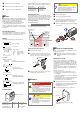
Switching function
Adjustment range
Hysteresis
Relay contact rating
1×10
-9
mbar … 100 mbar
Setpoint adjustable via
potentiometer, one floating,
normally open relay contact
(→ "Electrical Connection")
10% of reading
≤30 V, ≤0.5 ADC
RS232C interface
Data rate, data format
Connector
9600 baud, binary,
8 data bits, 1 stop bit
no parity bit, no handshake
(→ "Electrical Connection")
Further information on the RS232C interface → [1]
Display (353-572, 353-573) LCD matrix, 32×16 pixels,
with background illumination
Dimensions 17 mm × 12 mm
Pressure units
Selecting the pressure unit
mbar (default), Torr, Pa
via RS232C → [1]
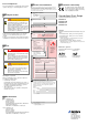
Supply
DANGER
The gauge must only be connected to power
supplies, instruments or control devices that
conform to the requirements of a grounded pro-
tective extra-low voltage (SELV-E according to
EN 61010). The connection to the gauge has to
be fused
1)
.