
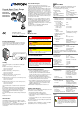
Manual

Voltage at gauge +24 VDC (+20 … +28 VDC)
(ripple ≤2 V
pp
)
2)
Power consumption
Standard
Degas
Emissions start (200 ms)
≤0.5 A
≤0.8 A
≤1.4 A
Fuse required
1)
≤1.25 AT
Power consumption
≤18 W (BPG402-S/-SL only)
Electrical connection D-Sub, 15 pins, male
Sensor cable Shielded, number of
conductors depend on
functions used.
Cable length (24 VDC)
≤35 m (0.25 mm²/conductor)
≤50 m (0.34 mm²/conductor)
≤100 m (1.0 mm²/conductor)
For operation with
RS232C interface
≤30 m
Materials on the vacuum side
Housing, supports,
screens
Feedthroughs
Insulator
Cathode
Cathode holder
Pirani element
stainless steel
NiFe nickel plated
glass
iridium, yttrium oxide (Y
2
O
3
)
molybdenum, platinum
tungsten, copper
Internal volume
DN 25 ISO-KF
DN 40 CF-R
≈24 cm
3
≈34 cm
3
Pressure max.
≤2 bar (absolute)
Admissible temperatures
Storage
Operation
Bakeout
Long tube
–20 … +70 °C
0 … +50 °C
80 °C
3)
150 °C
3)
Relative humidity
Year’s mean
During 60 days
≤65% (not condensable)
≤85% (not condensable)
Use indoors only
altitude up to 2000 m NN
Mounting orientation any
Type of protection IP 30
1)
INFICON controllers fulfill these requirements.
2)
Consider the voltage drop on the sensor cable.
3)
Flange temperature, without electronics unit, horizontally
mounted.
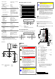
Dimensions
DN 25 ISO-KF
DN 40 CF-R
DN 40 CF-R
long tube
155.2
111
59
67
48
42
Weight 353-570, 353-572
353-571, 353-573
353-578
≈450 g
≈710 g
≈917 g
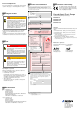
Measuring Signal vs. Pressure
1E+01
1E–01
1E–03
1E–05
1E–07
1E–09
1E+03
0.0
sensor error
overrange
1E+04
1E+02
1E+00
1E–02
1E–04
1E–06
1E–08
1E–10
1.02.03.04.05.06.07.08.09.010.0
underrange
Measuring signal U [V]
Pressure p [mbar]
p = 10
(U-7.75)/0.75+c
U p c
[V] [mbar] 0
[V] [Pa] 2
[V] [Torr] -0.125
where p pressure
U measuring signal
c constant (pressure unit dependent)
Gas Type Dependence
For gases other than air, the pressure in the indication range
p < 10
-3
mbar can be determined by a simple conversion:
p
eff
= C × pressure indicated
Gas
type
Calibration
factor C
Gas type Calibration
factor C
He
Ne
Kr
Ar
5.9
4.1
0.5
0.8
air, O
2
, CO, N
2
H
2
Xe
1.0
2.4
0.4
Installation
Vacuum Connection
DANGER
DANGER: overpressure in the vacuum system
>1 bar
Injury caused by released parts and harm
caused by escaping process gases can result if
clamps are opened while the vacuum system is
pressurized.
Do not open any clamps while the vacuum sys-
tem is pressurized. Use the type clamps which
are suited to overpressure.
DANGER
DANGER: protective ground
Incorrectly grounded products can be extremely
hazardous in the event of a fault.
The gauge must be electrically connected to the
grounded vacuum chamber. This connection
must conform to the requirements of a protective
connection according to EN 61010:
• CF connection fulfill this requirement
• For gauges with a KF flange, use a conduc-
tive metallic clamping ring
Caution
Caution: vacuum component
Dirt and damages impair the function of the
vacuum component.
When handling vacuum components, take ap-
propriate measures to ensure cleanliness and
prevent damages.
Caution
Caution: dirt sensitive area
Touching the product or parts thereof with bare
hands increases the desorption rate.
Always wear clean, lint-free gloves and use
clean tools when working in this area.
The gauge may be mounted in any orientation. To
keep condensates and particles from getting into the
measuring chamber, preferably choose a horizontal
to upright position.
The gauge is supplied with a built-in grid. For poten-
tially contaminating applications and to protect the
electrodes against light and fast particles, installation
of the optional baffle is recommended (→ [1]).
Vacuum connection free of grease.
Remove the protective lid and install the gauge to the
vacuum system. Keep the protective lid.
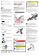
Electrical Connection (BPG402-S/-SL only)
Make sure the vacuum connection is properly made
(→ "Vacuum Connection").
If no connection cable is available, make one according
to the following diagram.
Common (power GND 24V supply)
Ground (housing, vacuum connection)
8
9
1
15
D-Sub,15 pins,
female,
soldering side
SP
TxD
RxD
Degas
42 kΩ
3
4
1
11
9
13
14
7
8
2
12
5
15
1.25 AT
24V
Degas
Ident.
RS232
10
-
-
-
1)
( )
Measuring
signal
-
V
S
Threshold value, SP
Filament status
6
Electrical connection
Pin 1 Relay switching function,
common contact
Pin 2 Measuring signal output 0 … +10 V
Pin 3 Threshold (setpoint)
1)
0 … +10 V
Pin 4 Relay switching function,
n.o. contact
Pin 5 Supply common 0 V
Pin 6 Not connected internally
Pin 7 Degas (active high) 0 V/+24 V
Pin 8 Supply (V
s
) +24 V
Pin 9 Relay filament status
common contact
2)
Pin 10 Gauge identification
Pin 11 Relay filament status,
n.o. contact
2)
Pin 12 Measuring signal common
Pin 13 RS232C, TxD
Pin 14 RS232C, RxD
Pin 15 Do not connect
1)
Do not connect pin 3 for normal operation of the
gauge. This pin is reserved for adjustment of the
setpoint potentiometer (
→ section "Switching
Function").
2)
→ section "Filament Status"
t i ma46e1- b
(2010-03)
Original: German tima46d1-b (2010-03)