
Manual
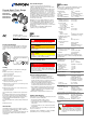

Connect the sensor cable to the gauge.
Secure the cable connector with the lock screws.
Connect the sensor cable to the controller.
Operation
When the voltage is supplied, the measuring signal is avail-
able between pins 2 (+) and 12 (–) (Relationship Measuring
Signal – Pressure
→ "Technical Data" and [1]).
BPG402-SD and -SP can also be operated via the
corresponding fieldbus interface (DeviceNet or Profibus)
(
→ [1] and [2] for further details and functions).
Allow for a stabilizing time of
≈10 minutes. Once the gauge
has been switched on, permanently leave it on irrespective of
the pressure.
Gas Type Dependence
The measurement value is gas dependent. The displayed
reading applies to dry air, O
2
, CO, and N
2
. For other gases, it
has to be converted (
→ "Technical Data" and [1]).
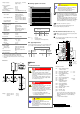
Display
(BPG402-S with part numbers 353-572 and 353-573)
Pressure reading
Pressure unit
Function display
(none) Pirani operation
E Emission 25 μA
E
. Emission 5 mA
D
Degas
Error display:
No error
(green background illumination)
Pirani sensor error
(red background illumination)
Bayard-Alpert sensor error
(red background illumination)
Internal data connection failure
(red background illumination)
Filament Status
Filament status LED
Filament status Emission Status LED
– off dark
Both filaments O.K. on green
One filament broken on green, flashing
Both filaments broken on red
A "Filament Status" relay contact is available at the sensor
cable connector
→ "Electrical Connection" (pins 9 and 11).
Filament status Relay contact
Both filaments O.K. energized
One filament broken deenergized
Both filaments broken deenergized
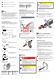
Switching Function
The BPG402-S/-SL have a manually adjustable switching
function with a normally open relay contact. The relay contact
is accessible at the sensor cable connector (pins 1 and 4).
The threshold value of the switching function can be set
within the pressure range 1×10
-9
mbar … 100 mbar via a
potentiometer "SETPOINT".
The following rule applies:
U
Threshold
= 0.75 × (log p
Setpoint
– c) + 7.75
Where constant c is pressure unit dependent
(
→ "Relationship Measuring Signal – Pressure").
Measuring signal
(Pressure p)
M
e
a
s
u
r
e
d
v
a
l
u
e
(Setpoint)
Off
Off
On
Switching
function
U
Threshold
Hysteresis
10% U
Threshold
Time t
Setting the Switching Function
Put the gauge into operation.
Connect the + lead of a voltmeter to the threshold
measurement point Pin 3 and its
– lead to a grounded
point (e.g. connector case or flange of the gauge).
max. ø2.5
Setpoint Pin 3 ( )
Using a screwdriver (max. ø2.5 mm), set the voltage
(Setpoint) to the desired value U
Threshold
.
Deinstallation
DANGER
DANGER: contaminated parts
Contaminated parts can be detrimental to health
and environment.
Before beginning to work, find out whether any
parts are contaminated. Adhere to the relevant
regulations and take the necessary precautions
when handling contaminated parts.
Caution
Caution: vacuum component
Dirt and damages impair the function of the vac-
uum component.
When handling vacuum components, take ap-
propriate measures to ensure cleanliness and
prevent damages.
Caution
Caution: dirt sensitive area
Touching the product or parts thereof with bare
hands increases the desorption rate.
Always wear clean, lint-free gloves and use
clean tools when working in this area.
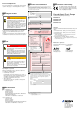
Vent the vacuum system.
Turn the gauge off at the power supply.
Unfasten the lock screws and unplug the sensor cable.
(If you are using BPG402-SD or -SP, unfasten and
unplug the interface cable, too (
→ [1] and [2]).
Remove the gauge from the vacuum system and install
the protective lid.
Protective lid
Maintenance, Troubleshooting
In case of severe contamination or a malfunction, the sensor
can be replaced (→ [1]).
Gauge failures due to contamination, as well as
expendable parts (filament), are not covered by the
warranty.
Adjusting the Gauge
The gauge is factory calibrated. If used under different
climatic conditions, at extreme temperatures, through aging
or contamination and after exchanging the sensor, the char-
acteristic curve can be offset and readjustment can become
necessary. Only the Pirani element can be adjusted and only
at atmosphere.
At the push of a button the digital value and thus the analog
output are adjusted electronically to +10 V at atmospheric
pressure.
Adjustment is necessary if
• at atmospheric pressure, the output signal is <+10 V
• the display reads < atmospheric pressure (if the gauge
has a display)
• at atmosphere, the digital value of the RS232C interface is
< atmospheric pressure
• when the vacuum system is vented, the digital value of the
RS232C interface reaches its maximum before the
measured pressure has reached atmosphere.
Activate the gauge and operate it for ≈10 minutes at
atmospheric pressure. If the gauge was operated within
the Bayard-Alpert range, a cooling-down time of
≈30 minutes is to be expected.
Press the button with a pin (max. ø1.3 mm) for 1 s.
max. ø1.3
Gauges with a display will show the reading
"1000 mbar".