Cover Page O P E R A T I N G M A N U A Composer Elite ™ Gas Concentration Monitor PN 074-566-P1B L
Title Page O P E R A T I N G M A N U A Composer Elite ™ Gas Concentration Monitor PN 074-566-P1B ® www.inficon.com ©2013 INFICON re achus@inficon.
Trademarks The trademarks of the products mentioned in this manual are held by the companies that produce them. Beckhoff® and TwinCAT® are registered trademarks of Beckhoff Automation GmbH. CIP™ is a registered trademark of Open DeviceNet Vendor Association, Inc. DeviceNet™ is a registered trademark of Open DeviceNet Vendor Association, Inc. Inconel® is a registered trademark of International Nickel Company.
Warranty WARRANTY AND LIABILITY - LIMITATION: Seller warrants the products manufactured by it, or by an affiliated company and sold by it, and described on the reverse hereof, to be, for the period of warranty coverage specified below, free from defects of materials or workmanship under normal proper use and service.
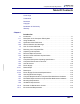
Composer Elite Operating Manual Table Of Contents Cover Page Trademarks Disclaimer Copyright Declaration Of Conformity Warranty Chapter 1 PN 074-566-P1B Introduction 1.1 1.1.1 1.2 1.2.1 1.2.2 1.3 1.3.1 1.4 1.4.1 1.4.2 1.5 1.5.1 1.5.2 1.5.3 1.5.4 1.5.4.1 Introduction. . . . . . . . . . . . . . . . . . . . . . . . . . . . . . . . . . . . . . . . . . . . . . . . . . 1-1 Description of the Composer Elite System . . . . . . . . . . . . . . . . . . . . . . . . . . 1-1 Using this Manual . . . . . . . . . . .
Composer Elite Operating Manual Chapter 2 Installation 2.1 2.1.1 2.1.1.1 Composer Elite Installation Guidelines. . . . . . . . . . . . . . . . . . . . . . . . . . . . . 2-1 Pressure, Temperature, and Tubing . . . . . . . . . . . . . . . . . . . . . . . . . . . . . . 2-1 Maximum Pressure . . . . . . . . . . . . . . . . . . . . . . . . . . . . . . . . . . . . . . . . . . . 2-1 2.1.1.2 Pressure and Tubing Size . . . . . . . . . . . . . . . . . . . . . . . . . . . . . . . . . . . . . . 2-2 2.1.1.
Composer Elite Operating Manual 3.3.2.6 Sensor Screen . . . . . . . . . . . . . . . . . . . . . . . . . . . . . . . . . . . . . . . . . . . . . . 3-10 3.3.2.7 Sensor Parameters Screen . . . . . . . . . . . . . . . . . . . . . . . . . . . . . . . . . . . . 3-12 3.3.3 3.3.3.1 Description of Rear Panel. . . . . . . . . . . . . . . . . . . . . . . . . . . . . . . . . . . . . . 3-14 Power Connector . . . . . . . . . . . . . . . . . . . . . . . . . . . . . . . . . . . . . . . . . . . . 3-14 3.3.3.
5.4.1.3 Message Router (02h) . . . . . . . . . . . . . . . . . . . . . . . . . . . . . . . . . . . . . . . . . 5-5 5.4.1.4 DeviceNet Object (03h) . . . . . . . . . . . . . . . . . . . . . . . . . . . . . . . . . . . . . . . . 5-5 5.4.1.5 Assembly Object (04h) . . . . . . . . . . . . . . . . . . . . . . . . . . . . . . . . . . . . . . . . . 5-6 5.4.1.6 Connection Object (05h) . . . . . . . . . . . . . . . . . . . . . . . . . . . . . . . . . . . . . . . 5-7 5.4.1.7 Acknowledge Handler Object (2Bh) .
Composer Elite Operating Manual Chapter 6 PN 074-566-P1B Composer Elite Multi-Sensor Software 6.1 6.2 6.2.1 6.2.2 6.2.3 6.2.4 6.3 6.3.1 6.3.2 6.3.3 6.3.4 6.3.5 6.3.6 6.3.7 6.3.7.1 Introduction. . . . . . . . . . . . . . . . . . . . . . . . . . . . . . . . . . . . . . . . . . . . . . . . . . 6-1 Hardware Requirements. . . . . . . . . . . . . . . . . . . . . . . . . . . . . . . . . . . . . . . . 6-1 Computer Requirements . . . . . . . . . . . . . . . . . . . . . . . . . . . . . . . . . . . . . . .
Composer Elite Operating Manual Chapter 9 Measurement and Theory 9.1 9.2 9.3 9.4 9.4.1 9.4.2 Speed of Sound and Gas Composition . . . . . . . . . . . . . . . . . . . . . . . . . . . . 9-1 Measuring the Speed of Sound . . . . . . . . . . . . . . . . . . . . . . . . . . . . . . . . . . 9-4 Composer Elite Overview. . . . . . . . . . . . . . . . . . . . . . . . . . . . . . . . . . . . . . . 9-6 Description of Subsystems. . . . . . . . . . . . . . . . . . . . . . . . . . . . . . . . . . . . . .
Composer Elite Operating Manual Chapter 1 Introduction 1.1 Introduction Composer Elite™ is designed to measure the precursor concentration of binary gases. It is optimized for operation at pressures as low as 26.66 kPa [200 Torr] and temperatures as high as 65°C. The Composer Elite System provides unsurpassed precision and reproducibility when measuring small concentrations of heavy molecular weight components in a lower molecular weight carrier gas. 1.1.
Composer Elite Operating Manual 1.2 Using this Manual Please take a moment to read the following. 1.2.1 Symbols and their Definitions NOTE: Notes provide additional information about the current topic. HINT: Hints provide insight into product usage. CAUTION Failure to heed these messages could result in a malfunction or damage to Composer Elite. WARNING Failure to heed these messages could result in physical injury.
Composer Elite Operating Manual 1.2.2 General Cautions and Warnings WARNING - Risk Of Electric Shock Dangerous voltages are present inside the 24 V power supply whenever the power cord is connected. Do not open the power supply casing. CAUTION Composer Elite contains circuitry susceptible to transient mains voltages. Disconnect the power cord whenever making any interface connections. CAUTION Do not open the casing of any component of the Composer Elite System.
Composer Elite Operating Manual 1.3 How To Contact INFICON Worldwide customer support information is available under Contact >> Support Worldwide at www.inficon.com Sales and Customer Service Technical Support Repair Service If you are experiencing a problem with your Composer Elite or Composer Elite Multi-Sensor software, please have the following information readily available: The Sales Order or PO number for the Composer Elite purchase.
Composer Elite Operating Manual 1.4 Unpacking and Inspection 1 If Composer Elite has not been removed from its shipping container, do so now. Do not discard the packing materials before reading the following steps. 2 Carefully examine Composer Elite for damage that may have occurred during shipping. This is especially important if you notice obvious rough handling on the outside of the container. Immediately report any damage to the carrier and to INFICON.
Composer Elite Operating Manual 1.4.1 Parts and Options Overview Sensor Control Unit . . . . . . . . . . . . . . . . . . . . . . PN 761-220-G1 Acoustic Sensor Standard . . . . . . . . . . . . . . . . . . . . . . . . . . . . PN 761-219-G1 High Flow . . . . . . . . . . . . . . . . . . . . . . . . . . . PN 761-219-G2 NOTE: The High Flow Acoustic Sensor is identified by a "G2" marking on the inlet tube nut. Interconnect Cable, 15 ft. (4.6 m). . . . . . . . . . . . PN 600-1447-P15 Ship Kit. . . . . . . . . . .
Composer Elite Operating Manual 1.4.2 Sensor Control Unit Power-Up Verification It is not necessary to have Acoustic Sensors or communications cables connected to the Sensor Control Unit at this time. 1 Set the power switch on the rear panel of the Sensor Control Unit to the 0 (OFF) position. (See Figure 3-8 on page 3-14.) 2 Using the INFICON (optional) 24 V power supply, or a power supply as defined in section 1.5.
Composer Elite Operating Manual 1.5 Specifications 1.5.1 Composer Elite System Operating Specifications Operating Pressure Range . . . . . . . 26.7 to 133.4, kPa [200-1000 Torr] absolute Routine Overpressure Rating. . . . . . Up to 202.7 kPa [1520 Torr] absolute Maximum Overpressure . . . . . . . . . . 826.2 kPa [6200 Torr] absolute. Pressure over 826.2 kPa may damage Acoustic Sensor diaphragms. Gas Flow Range Standard Acoustic Sensor (for H2 and He carrier gas). . . . .
Composer Elite Operating Manual 1.5.2 Composer Elite Sensor Control Unit Size H x W x D . . . . . . . . . . . . . . . . . 132.8 x 213.4 x 254 mm (5.23 x 8.4 x 10.0 in.) 3U Half Rack Measurement Channels . . . . . . . . . . Up to 5 Acoustic Sensors supported with 1 Sensor Control Unit Required Connector Clearance . . . . 76.2 mm (3 in.) at rear panel for electrical connector removal or insertion Rack Mount . . . . . . . . . . . . . . . . . . . Optional; Full Rack Extender, PN 782-900-007 Weight . . . . . .
Composer Elite Operating Manual 1.5.3 Acoustic Sensor Size . . . . . . . . . . . . . . . . . . . . . . . . . 124 mm (4.88 in.) between VCR-4 seal surfaces. Maximum outline dimensions W x H x D (with gaskets and caps) 77.7 x 149.9 x 185.4 mm (3.06 x 5.90 x 7.30 in.) Measurement Principle . . . . . . . . . . Precursor concentration determined by precision measurement of speed of sound in a temperature controlled volume.
Composer Elite Operating Manual Mounting Requirements . . . . . . . . . . M4-0.7 (4), max. screw penetration 6.4 mm (0.25 in.) depth threaded holes provided. Because the attachment to each system widely varies, a mounting bracket must be customer fabricated. Weight . . . . . . . . . . . . . . . . . . . . . . . Approximately 2.3 kg (5.1 lb.) Storage Temperature Range . . . . . . -10 to +70°C (14 to 158°F) Humidity Range . . . . . . . . . . . . . . . . 0 to 80% RH non-condensing 1.5.
Composer Elite Operating Manual 1.5.4.2 Rated Input Operational Voltage Range . . . . . . . 100 to 240 V(ac) +/- 10% (ac) Frequency Range. . . . . . . . . . . . . . . 47 to 63 Hz In-rush Current . . . . . . . . . . . . . . . . . <60 A at 230 V(ac) input, 25°C ambient cold start Input Current . . . . . . . . . . . . . . . . . . 2.5 A max. Overvoltage . . . . . . . . . . . . . . . . . . . 110% - 130% of nominal (Cycle input power to reset) Unit Mains Connector. . . . . . . . . . . .
Composer Elite Operating Manual 1.5.6 Computer Requirements for Composer Elite Multi-Sensor Software Processor . . . . . . . . . . . . . . . . . . . . . 1 GHz Memory . . . . . . . . . . . . . . . . . . . . . . 512 MB RAM Display Resolution . . . . . . . . . . . . . . 1280 x 1024 Storage . . . . . . . . . . . . . . . . . . . . . . . 5 MB of Hard Drive Space Operating System. . . . . . . . . . . . . . . Windows XP (SP3), Windows 7 Communications. . . . . . . . . . . . . . . .
Composer Elite Operating Manual 1.5.10 Perimeter for Maintenance Access Acoustic Sensor to be removed from the process gas tubing (Swagelok VCR-4 fittings) require side-to-side or top-to-bottom clearance of 16 cm (6 in.) for wrench rotation. Interconnect Cable to be removed or replaced from either Acoustic Sensor or Sensor Control Unit requires 8 cm (3 in.) clearance. Sensor Control Unit to be removed from rack, full 30.5 cm (12 in.) length required. 1.5.
Composer Elite Operating Manual Chapter 2 Installation 2.1 Composer Elite Installation Guidelines The requirements and recommendations in section 2.1.1, section 2.1.2, and section 2.1.3 must be reviewed and understood before Composer Elite is installed as described by section 2.2, Composer Elite Installation, on page 2-8. 2.1.1 Pressure, Temperature, and Tubing 2.1.1.1 Maximum Pressure Reliable measurement of concentration to absolute pressures as low as 26.
Composer Elite Operating Manual 2.1.1.2 Pressure and Tubing Size The Composer Elite System is designed to operate with the gases in the Reactor's process tubing at a pressure of 26.66 to 133.3 kPa (200 to 1000 Torr). The inner diameter of the inlet and outlet tubes on the Standard and High Flow Acoustic Sensors were designed to optimize performance at low pressures; however, the Reactor’s process tubing may be of any appropriate size without degrading Composer Elite performance. 2.1.1.
Composer Elite Operating Manual 2.1.2 Grounding and Shielding 2.1.2.1 Power Supply Grounding Requirement WARNING - Risk Of Electric Shock The Composer Elite 24 V Power Supply must be connected to a grounded socket outlet using a three-conductor power cable with ground terminal. The Composer Elite 24 V power supply (optional) is connected to ground through a sealed three-conductor power cable, which must be plugged into a socket outlet with a protective ground terminal.
Composer Elite Operating Manual 2.1.2.3 Composer Elite System Grounding Requirement CAUTION The Sensor Control Unit and Acoustic Sensor must be grounded for proper performance of Composer Elite. The following grounding method is recommended: 1 Verify that the Reactor is connected to a good, reliable earth ground (refer to section 2.1.2.2, Earth Ground Requirement, on page 2-3). Use a solid copper strap, at least 0.08 cm (0.030 in.) thick by 2.5 cm (1 in.
Composer Elite Operating Manual 2.1.2.4 Electrical Interference Reduction When Composer Elite is integrated into a deposition system, each cable connection is a potential path for electrical noise to be conducted to the Sensor Control Unit or Acoustic Sensor. The possibility of external electrical interference problems can be greatly reduced by adhering to the following guidelines: Make certain the Sensor Control Unit and Acoustic Sensor are properly grounded. (Refer to section 2.1.2.
Composer Elite Operating Manual 2.1.3 Composer Elite Location Selection 2.1.3.1 Selecting The Acoustic Sensor Location Locate the Acoustic Sensor at a point after the Dilution Flow gas is added and before the Back Pressure Controller. (See Figure 2-2 on page 2-6.) This creates the environment with the most stable pressure and flow conditions for best Composer Elite stability.
Composer Elite Operating Manual The Interconnect Cable route should be planned to minimize external electrical interference. (Refer to section 2.1.2.4, Electrical Interference Reduction, on page 2-5.) 2.1.3.2 Selecting The Sensor Control Unit Location The Sensor Control Unit is designed for bench top operation or mounting in a standard 48.26 cm (19 in.) rack using the optional Full Rack Extender (PN 782-900-007).
Composer Elite Operating Manual 2.2 Composer Elite Installation 2.2.1 Installing The Sensor Control Unit in a 19 in. (48.26 cm) Rack Install the Sensor Control Unit in a standard 48.26 (19 in.) rack using the optional Full Rack Extender (PN 782-900-007). 1 Assemble the two 7.62 x 12.7 cm (3 x 5 in.) Extender Kit side panels and the larger front and rear panels into a box configuration using the eight 6-32 flat-head screws.
Composer Elite Operating Manual 2.2.2 Installing The Acoustic Sensor WARNING Many gases used for film growth are toxic at very low exposure levels. CAUTION Although the Acoustic Sensor was thoroughly leak tested at the factory, periodic leak testing of the Acoustic Sensor is recommended. See section 7.2, Leak Test Procedures, on page 7-1. 1 Remove the caps from the VCR-4 fittings on the Acoustic Sensor's inlet and outlet tubes by holding the fitting stationary with a 5/8 in.
Composer Elite Operating Manual 4 Install new VCR-4 gaskets (see section 7.3, Spare Parts, on page 7-5) into the VCR fittings on the inlet and outlet tubes. NOTE: Gaskets with retainers are directional and easily snap over the face of the gland seal. (See Figure 2-4.) Figure 2-4 Installation of gasket with retainer on gland 5 Connect the Acoustic Sensor to the process tubing using a 5/8 in.
Composer Elite Operating Manual 2.2.3 Installing Interconnect, Power Supply, and Communications Cables 1 Set the Sensor Control Unit power switch to 0 (OFF). (See Figure 2-5.) CAUTION Composer Elite contains circuitry susceptible to transient mains voltages. Make certain Composer Elite is powered down whenever making any interface connections.
Composer Elite Operating Manual 5 Insert the 24 V Power Supply output-cable connector into the Sensor Control Unit power connector until it locks in place. (Refer to Figure 2-5.) 6 Connect the power cord to the 24 V Power Supply inlet receptacle. 7 Connect the power cord plug to Mains power. (Refer to section 1.5.4.2, Rated Input, on page 1-12.) 2.2.4 Installing Composer Elite Multi-Sensor Software PN 074-566-P1B See section Chapter 6, Composer Elite Multi-Sensor Software, on page 6-1.
Composer Elite Operating Manual Chapter 3 Operation 3.1 Initialization and Setup Application-specific parameter values must be entered, or downloaded, to Composer Elite. The parameters include the gases’ Specific Heat Ratios and Molecular Weights. 3.1.1 Parameter Entry Parameter values may be downloaded to Composer Elite by: Composer Elite Multi-Sensor Software, see Chapter 6. Remote communications using the protocol and commands in Chapter 5. Composer Elite front panel. 3.1.1.
Composer Elite Operating Manual control knob to change the value for that digit. To save the changes, press Save. To cancel changes, press Cancel. See Figure 3-2 for an example of screen layout while editing parameters. Figure 3-2 Editing parameters 3.2 Calibration For many applications, Factory Zero is sufficient to provide the needed levels of accuracy and reproducibility. Refer to section 4.1.3, How is Performance Affected if I Use the Factory (Reference) Zero Value?, on page 4-2. 3.2.
Composer Elite Operating Manual 3.2.2 Special Tools and Materials Flowing a pure gas through the Acoustic Sensor at process pressure and flow rate is required for calibration. NOTE: For guaranteed safe operation, a calibrated high-performance mass spectrometer leak detector should be used to check leak integrity whenever the Acoustic Sensor has been removed and reinstalled. 3.2.3 How to Calibrate 1 In the Sensor Parameters pane, set ALLOW USER ZERO to YES.
Composer Elite Operating Manual 3.3 How To Use Composer Elite The following sections explain how to start, stop, and power down Composer Elite. A description and purpose of the operating modes, displays, and system I/O connectors is also provided. 3.3.1 How to Power Up and Power Down Composer Elite Operating Composer Elite requires a 24 V power connection. Refer to section 1.5.4 on page 1-11 for complete power specifications. To power up Composer Elite, 1 Connect the 24 V(dc) power supply (see section 1.
Composer Elite Operating Manual 3.3.2 Composer Elite Screen Descriptions Boot Screen, see section 3.3.2.1 Indicators Displayed On Screens, see section 3.3.2.2 on page 3-6 Overview Screen, see section 3.3.2.3 on page 3-6 System Overview Screen, see section 3.3.2.4 on page 3-8 Errors and Warnings Screen, see section 3.3.2.5 on page 3-9 Sensor Screen, see section 3.3.2.6 on page 3-10 Sensor Parameters Screen, see section 3.3.2.7 on page 3-12 3.3.2.
Composer Elite Operating Manual 3.3.2.2 Indicators Displayed On Screens AT TEMP . . . . . . . . . . . . . . . . . . . . . Indicates that the temperature is within ±0.002°C of Temperature Setpoint 1 and ±0.005°C of Temperature Setpoint 2. The text is displayed in green. NEAR TEMP . . . . . . . . . . . . . . . . . . Indicates that the current temperature is near the desired temperature for Temperature Setpoint 1. The text is displayed in blue. BELOW TEMP . . . . . . . . . . . . . . . . .
Composer Elite Operating Manual ERRORS, WARNINGS, or ERRS & WRNS may be displayed, depending on whether errors, warnings, or both are present (see section 3.3.2.5). If no errors or warnings are present, this area will be blank. Figure 3-3 Overview screen Buttons 1 through 5 represent Sensor 1 Data, Sensor 2 Data, etc. To enlarge and view data for an individual sensor, press the button associated with that sensor number to enter the Sensor screen. For example, press Sensor 1 Data to view data for sensor 1.
Composer Elite Operating Manual 3.3.2.4 System Overview Screen The System Overview screen displays information about the system’s hardware. It displays remote communication port information such as the DeviceNet address and the RS-232 Baud rate. It also displays the firmware version, hardware version, and the version number and status for any installed sensor cards. Figure 3-4 System Overview screen The DeviceNet address can be adjusted to values of 0-63, appropriate to the network topology.
Composer Elite Operating Manual 3.3.2.5 Errors and Warnings Screen The Errors and Warnings screen displays current hardware errors or warnings. The error is listed with its sensor number (if applicable) and its error code. Use the control knob to scroll through the list of errors and/or warnings. At the bottom of the screen is a description of the highlighted error/warning. Details on system errors and warnings can be found in Table 5-22 on page 5-32 and Table 5-23 on page 5-34.
Composer Elite Operating Manual 3.3.2.6 Sensor Screen On the Overview screen, press Sensor Data to display the Sensor screen (see Figure 3-6). Data displayed on the Sensor screen is for an individual sensor. Data includes Concentration (Conc), FACTORY ZERO status, Temp 1 and Temp 2. Indicators (described in section 3.3.2.2 on page 3-6) display when appropriate. Errors, Warnings or Errors & Warnings may be displayed, depending on whether errors, warnings, or both are present.
Composer Elite Operating Manual Pressing Advanced Data displays acoustic information when a cell is attached. This information displayed includes: Frequency . . . . . . . . . . . . . . . . . Acoustic cell frequency. Amplitude . . . . . . . . . . . . . . . . . Signal amplitude [Volts RMS] of the measured frequency. R2 . . . . . . . . . . . . . . . . . . . . . . . . Coefficient of Determination - Lorentzian curve's "goodness of fit" (0<=R2<=1 where 1 is perfect curve fit). Q. . . . . . . . . . . . . . . . .
Composer Elite Operating Manual Table 3-1 Sensor card measurement modes Mode Description Ready Sensor card is not attempting to measure a resonance. Baseline Search Track QTrack Acoustic signal level re-initialization is being performed before Search mode is entered. Sensor card is looking for an acoustic resonance to track/measure. (Frequency, Amplitude, R2 and RAV should be ignored while in Search mode.) Sensor card is tracking/measuring a resonance.
Composer Elite Operating Manual Allow user zero . . . . . . . . . . . . . . . . Is a user-defined reference zero allowed? Default value is No. Temperature Setpoint 1 . . . . . . . . . Sets the Acoustic Sensor’s resonant chamber temperature (°C). Allowable range is 30.0 to 65.0°C. Default is 40°C. Temperature Setpoint 2 . . . . . . . . . Temperature setpoint (°C) of the inlet tube. Allowable range is 30.0 to 68.0°C.
Composer Elite Operating Manual 3.3.3 Description of Rear Panel The rear panel of Composer Elite is shown in Figure 3-8. Figure 3-8 Rear panel of Composer Elite Ground Stud RS-232 Connector Power Switch Sensor Card Connector DeviceNet Connector Power Connector I/O Slot Control Sensor 5 Sensor 4 Sensor 3 Sensor 2 Sensor 1 Slot Slot Slot Slot or I/O Slot Slot 3.3.3.1 Power Connector A 4-pin connector used for connection to a 24 V(dc) power supply. Refer to section 1.5.
Composer Elite Operating Manual 3.3.3.5 Control Slot This slot is occupied by the Control card. RS-232 and DeviceNet connectors are located on the rear panel of the Control card (see Chapter 5, Remote Communications for information regarding RS-232 and DeviceNet). 3.3.3.6 Sensor 5 - I/O Slot This slot is currently available only for an additional Sensor card. 3.3.3.7 Sensor Slots 1 - 4 PN 074-566-P1B These slots are reserved for the Sensor card(s).
Composer Elite Operating Manual PN 074-566-P1B This page is intentionally blank.
Composer Elite Operating Manual Chapter 4 Applications Guide 4.1 Advice and Tips The following paragraphs review many common questions encountered during setup and operation. 4.1.1 What is the Required Warm Up Time? Once the setpoint for the Acoustic Sensor’s temperature is altered, it will take up to thirty minutes for a single Acoustic Sensor’s temperature to settle around the operating point.
Composer Elite Operating Manual The correct (user set) Reference Zero is retained until a new Reference Zero is established, the Setpoint Temperature is changed or new carrier gas parameters are entered. NOTE: STEADY and AT TEMP must be visible when completing the Calibration process. This indicates the measurement conditions are stable and a relative equilibrium has been reached.
Composer Elite Operating Manual 4.1.4 What To Do when the Specific Heat Ratio for a Gas is Unknown Quantitative accuracy for an acoustic measurement technique partially depends on accurate knowledge of the Specific Heat Ratio, , of the individual gas species. While this ratio is known for many pure common gases, little information is available on many of the complex Precursor molecules. The information currently available is given in Table B-1 on page B-1.
Composer Elite Operating Manual 4.1.5 What is the Ideal Operating Environment? In an ideal operating environment, parameters that influence the concentration measurement do not change. Most Reactors can be configured so that the pressure and flow through the Acoustic Sensor are held constant by independent controllers. The precursor’s fluence into the Reactor can be maintained or changed without altering the total flow and pressure through the Acoustic Sensor.
Composer Elite Operating Manual 4.1.7 What is the Effect of Flow Variation? There is virtually no flow induced effect on concentration measurement in the Composer Elite System except at the highest flow rates, see Figure 4-3, the pressure drop across the Acoustic Sensor is about 12 Torr [1.60 kPa] at 2000 sccm for the Standard sensor or 6 Torr [0.80 kPa] for the High Flow sensor. HINT: Large variations in flow rate will cause a shift in the zero concentration point.
Composer Elite Operating Manual sound. The resonant method does not lose accuracy because of uncertainty of guessing when the center of a low energy acoustic pulse packet precisely leaves the Sender and reaches the Receiver. See Figure 4-4. For a TOF instrument to achieve resolution equivalent to Composer Elite (1 part in 50,000), it must achieve time measurement precision of 3 nanoseconds.
Composer Elite Operating Manual 4.1.9 What is the Long Term Stability of this Measurement System? There does not appear to be any trend that might lead to any unexpected wear or degradation with time. This data is not corrected for zero offsets due to atmospheric pressure variations over the test period.
Composer Elite Operating Manual 4.1.10 What Happens if the Reference Zero is Improperly Set? If the Reference Zero is set when the conditions are wrong, i.e., not completely purged of precursor gas: 1 A permanent concentration offset is introduced equal to the residual precursor concentration when the new Reference Zero is applied. This is not corrected until a proper Reference Zero is performed. 2 The sensitivity is altered, leading to an error proportional to the concentration.
Composer Elite Operating Manual 4.1.11 How to Sample Flow with a Composer Elite When the flow through a process pipe exceeds the Acoustic Sensor’s 2000 sccm limit, sampling of the process is required. In our experience, bypassing some of the process gas through the Acoustic Sensor can compromise Composer Elite precision, long term accuracy and add noise due to pressure and flow fluctuations.
Composer Elite Operating Manual PN 074-566-P1B This page is intentionally blank.
Composer Elite Operating Manual Chapter 5 Remote Communications 5.1 Introduction Composer Elite supports RS-232C and DeviceNet communications, and may be remotely controlled, programmed or interrogated. This is accomplished through remote communications and the use of a remote command set. Composer Elite will respond to messages that contain these commands. It will accept and operate one message at a time.
Composer Elite Operating Manual Only serial communications baud rate of 115,200 is supported. The communications interface operates using the DCE (Data Communications Equipment) configuration. NOTE: Some RS-232 hardware/software combinations may occasionally cause a command to not be recognized by Composer Elite. Consequently, all communications should include an automatic retry procedure if a response is not received within three seconds.
Composer Elite Operating Manual 5.4 DeviceNet Communications For DeviceNet Messaging, the transmit/receive message count field is used by the process transmitting the message to indicate that data is available to read and process. The application will populate the Composer Elite command field with the data to be transmitted to Composer Elite and increment the Transmit Message Count field. This will indicate to Composer Elite that there is a command ready to be processed.
Composer Elite Operating Manual 5.4.1 DeviceNet Objects 5.4.1.1 CIP Type Definitions Refer to ODVA™ CIP™ classes. 5.4.1.2 Identity Objects (01h) Table 5-2 shows the Identity objects.
Composer Elite Operating Manual 5.4.1.3 Message Router (02h) Not used. 5.4.1.4 DeviceNet Object (03h) DeviceNet objects are shown in Table 5-3.
Composer Elite Operating Manual 5.4.1.5 Assembly Object (04h) This assembly object uses static assemblies and holds the Composer Elite I/O. The assembly instance IDs used are in the vendor specific range. Specifics on the CE Out(Command) and CE IN(Response) are detailed later in the section 5.5.1, Command, on page 5-22 and section 5.5.2, Response, on page 5-22. NOTE: This is the object used to interact with Composer Elite Command & Response messaging.
Composer Elite Operating Manual 5.4.1.6 Connection Object (05h) Connection objects are shown in Table 5-6. The supported services are: Class - Get Attribute Single (Revision, UINT, 0001h) Instance - Get/Set Attribute Single PN 074-566-P1B Table 5-6 Instance #1,#10...
Composer Elite Operating Manual Table 5-7 Instance #2 (Poll or "COS/Cyclic Consuming") Name Access Type Comments 1 State Get USINT 0 = Nonexistent 1 = Configuring 2 = Waiting for Connections ID 3 = Established 4 = Timeout 2 Instance Type Get USINT 0000h (I/O Connection) 3 Transport Class Trigger Get BYTE 82h = Server, Polled, Class 2 80h = Server, COS/Cyclic, Class 0, No Ack. 82h = Server, COS/Cyclic, Class 2, Ack.
Composer Elite Operating Manual Table 5-8 Instance #3 (Bit-Strobe) # Name Access Type Comments 1 State Get USINT 0 = Nonexistent 1 = Configuring 2 = Waiting for Connections ID 3 = Established 4 = Timeout 2 Instance Type Get USINT 0001h (I/O Connection) 3 Transport Class Trigger Get BYTE 82h (Transport class and Trigger Server, Cyclic, Class 2) 4 Produced Connection ID Get UINT - 5 Consumed Connection ID Get UINT - 6 Initial Comm Characteristics Get BYTE Produces over messa
Composer Elite Operating Manual Table 5-9 Instance #4 (COS/Cyclic Producing) # Name Access Type 1 State Get USINT 0 = Nonexistent 1 = Configuring 2 = Waiting for Connections ID 3 = Established 4 = Timeout 2 Instance Type Get USINT 0001h (I/O Connection) 3 Transport Class Trigger Get BYTE 00h = Client, Cyclic, Class 0, No Ack. 10h = Client, COS, Class 0, No Ack. 02h = Client, Cyclic, Class 2, Ack. 12h = Client, COS, Class 2, Ack.
Composer Elite Operating Manual 5.4.1.7 Acknowledge Handler Object (2Bh) The supported services are: Class - Get Attribute Single (Revision, UINT, 0001h) Instance - Get/Set Attribute Single Table 5-10 Instance Attribute (01h) # Name Access Type Comments 1 Acknowledge Timer Get/Set UINT 16ms 2 Retry Limits Get/Set USINT 01h 3 Producing Connection Instance Get UINT 04h 5.4.1.
Composer Elite Operating Manual Table 5-11 Instance Attributes (01h) # 100 Name Access Type Comments I/O Data Format Get/Set UINT 0 = INFICON Messaging 1 = Sensor 1 Data Set 2 = Sensor 2 Data Set 3 = Sensor 3 Data Set 4 = Sensor 4 Data Set 5 = Sensor 5 Data Set 6 = All 5 Sensor Card Data Set 7 = Sensors 1,2,3 Err/Wrn Data Set 8 = Sensors 4,5 Err/Wrn Data Set 9 = All 5 Sensor Card Concentration 5.4.2 DeviceNet Data Sets 5.4.2.
Composer Elite Operating Manual 5.4.2.2.2 Sensor 1-5 Data Set All of the basic and advanced data associated with a single sensor. The data set can be requested for any of the 5 possible sensors.
Composer Elite Operating Manual Table 5-13 Sensor 1-5 data set (continued) Name Range Data Type Note Standard Error Float Q Float PWM 1 Integer PWM 2 Integer Acoustic Gain Byte D Gain Heater 1 Float I Gain Heater 1 Float P Gain Heater 1 Float D Gain Heater 2 Float I Gain Heater 2 Float P Gain Heater 2 Float RAV Float Controller Card Board Temperature Float Sensor Card Board Temperature Float NOTE: RAV value is calculated during the Track and Q Track measurement modes.
Composer Elite Operating Manual PN 074-566-P1B Table 5-14 All sensor card data set (continued) Name Range Sensor 1 Temperature 2 30.0 – 65.0 C Data Type Note Float The current temperature value of second temperature sensor.
Composer Elite Operating Manual Table 5-14 All sensor card data set (continued) 5 - 16 Name Range Sensor 3 SS, LS, MH1/PC, MH2/UZ, AT, CS, ER, RS, BM, WA Refer to Table 5-18 Data Type Note Integer Sensor 3 Measurement Mode IDLE = 0 READY =1 SEARCH = 2 TRACK = 3 QTRACK = 4 BASELINE = 6 Encoded Sensor 3 Concentration 0.0 – 100.0 mole % Float The current concentration value. Sensor 3 Temperature 1 30.0 – 65.0 C Float The current temperature value of first temperature sensor.
Composer Elite Operating Manual PN 074-566-P1B Table 5-14 All sensor card data set (continued) Name Range Sensor 4 Heater 1 Status 0-6 Data Type Note Short 0 = Off 1 = Not at temp 2 = At temp 3 = Failed 4 = Cable Disconnected 5 = Near Temp 6 = Over Temp Sensor 4 Heater 2 Status 0-6 Short 0 = Off 1 = Not at temp 2 = At temp 3 = Failed 4 = Cable Disconnected 5 = Near Temp 6 = Over Temp Sensor 4 Sample Number 0 – 255 Byte The current sample number.
Composer Elite Operating Manual 5.4.2.2.4 Sensors 1,2,3 Error/Warning Data Set This data set returns a compound set of current data values for three of the five sensor cards. Table 5-15 Sensors 1,2,3 error/warning data set Cached Data Set Data Type Note 7 Byte Numeric value of the data set cached. 0 – 0x1F Byte Bitwise: Bits 0 – 4 set indicate sensor board 1 – 5 present, respectively. Refer to Table 5-18 Integer Status bits Refer to Table 5-18 SS bit is not relevant in the data set format.
Composer Elite Operating Manual Table 5-15 Sensors 1,2,3 error/warning data set (continued) Name Range Sensor 3 SS, LS, MH1/PC, MH2/UZ, AT, CS, ER, RS, BM, WA Data Type Note Refer to Table 5-18 Integer Status bits Refer to Table 5-18. SS bit is not relevant in the data set format. Sensor 3 Errors ------ Integer Current error value. Refer to Table 5-22 for a complete description of the errors. Sensor 3 Warnings ------ Integer Current warning value.
Composer Elite Operating Manual Table 5-16 Sensors 4,5 error/warning data set Name Range Data Type Note Sensor 4 Heater 1 Current Drawn Float Sensor 4 Heater 2 Current Drawn Float Sensor 5 SS, LS, MH1/PC, MH2/UZ, AT, CS, ER, RS, BM, WA Refer to Table 5-18 Integer Status bits Refer to Table 5-18. SS bit is not relevant in the data set format. Sensor 5 Errors ------ Integer Current error value. Refer to Table 5-22 for a complete description of the errors.
Composer Elite Operating Manual Table 5-17 5 sensors' concentration data set (continued) Name Range Data Type Note Sensor 2 Concentration 0.0 – 100.0 mole % Float Sensor 3 SS, LS, MH1/PC, MH2/UZ, AT, CS, ER, RS, BM, WA Refer to Table 5-18 Integer Sensor 3 Concentration 0.0 – 100.0 mole % Float Sensor 4 SS, LS, MH1/PC, MH2/UZ, AT, CS, ER, RS, BM, WA Refer to Table 5-18 Integer Sensor 4 Concentration 0.0 – 100.
Composer Elite Operating Manual 5.5.1 Command This section describes the command format. See section 5.6, Communication Commands, on page 5-27 for details on specific command IDs. The message received by Composer Elite contains a data packet preceded by a length and terminated by a checksum. Composer Elite will always send a response to any command it receives. 5.5.1.1 Command Packet (Host to Composer Elite Message) Length . . . . . . . . . . . . . . . . . . . . . . .
Composer Elite Operating Manual 5.5.2.1 Response Packet (Composer Elite to Host Message) Length . . . . . . . . . . . . . . . . . . . . . . . 2 bytes Low / High (not including checksum or length bytes). Numeric value representing the number of characters in the response. Two byte values, high and low order, are required to represent this number. In order of transmission, the low byte will precede the high byte. Command .
Composer Elite Operating Manual 12 (0x0C) . . . Uninstalled sensor number 17 (0x11) . . . Message length incorrect for given command 18 (0x12) . . . Message checksum invalid* 19 (0x13) . . . Sent data out of range 20 (0x14) . . . Unknown command 21 (0x15) . . . Data requested not currently available 22 (0x16) . . . Message timeout. Entire message not received in 3 seconds.* 23 (0x17) . . . Action could not be completed. (e.g.
Composer Elite Operating Manual Table 5-18 Status bit (continued) Status Name Bit UZ Zero Reference (Bit 28) Value Data Type 0|1 Bit Note When sensor number is 1-5: 0= Sensor is using Factory Zero. 1= Sensor is using User Zero. When Sensor Number is 0: 0= All the sensors are using the Factory Zero. 1= At least one of the sensors is using the User Zero. AT At Temperature (Bit 27) 0|1 Bit When sensor number is 1-5: 0= Sensor is not at temperature (neither heater is at temperature).
Composer Elite Operating Manual Table 5-18 Status bit (continued) Status Name Bit BM Boot Monitor (Bit 22) Value Data Type 0|1 Bit Note When sensor number is 1-5: 0= Sensor is currently running application code. 1= Sensor is currently running boot monitor code. When Sensor Number is 0: 0= All of the sensors are running application code. 1= At least one of the sensors is currently running boot monitor code.
Composer Elite Operating Manual 5.6 Communication Commands The following shows a summary of the available commands. The headers/trailers are assumed. H. . . . . . . Hello. Returns the model and software version number. (See section 5.6.1. and section 5.7.1 on page 5-37.) Q. . . . . . . Query. Interrogates the programmable parameters and returns the value of parameter requested. (See section 5.6.2 on page 5-28 and section 5.7.2 on page 5-37.) U. . . . . . . Update.
Composer Elite Operating Manual 5.6.1 Hello Command Message = H Command ID = 0-1 Sensor = 0-5 The control card is represented with a 0. Internal Parameter = 0 Response = | See Table 5-19. Table 5-19 Hello command response H Name Command ID Value Range (low/high) Data Type Note 0 Hello String Composer Elite ver. xx.xx.xx 8x21 String The model and version numbers of Composer Elite, 'Composer Elite ver xx.xx.xx' where xx.
Composer Elite Operating Manual 5.6.3 Update Commands Message = U Command ID = See Command ID in Table 5-20. Sensor = 1-5 Internal Parameter = 0 Data = See range column in Table 5-20. Response = None (header and trailer only) Table 5-20 Query & Update commands Q&U Name Command ID Range (low/high) Data Type Note Restrictions Carrier Molecular Weight 1.000 1000.
Composer Elite Operating Manual 5.6.4 Status Commands Message = S ()(|) Command ID = See Command ID in Table 5-21. Sensor = 1-5. Use 0 for Command S7. (Temperature Zone) = 1-2 Used only with Command S1. 0 if unused. (Heater ID) = 1-2 Used only with Command S3. 0 if unused. PN 074-566-P1B Response = |||| See Data Range & Type columns in Table 5-21.
Composer Elite Operating Manual Table 5-21 Status commands S Name Command ID 0 Current Data Parameter Range (low/high) Data Type Reserved (U20 - Bit 31) Must always be 0. Bit Pattern (U20 - Bit 30) PN 074-566-P1B Note The value of the 4 Byte word returned. Measurement Mode (U20 - Bit 29) 0-6 Encode 0 = Idle 1 = Ready 2 = Search 3 = Track 4 = Quick Track 6 = Baseline Concentration (U20 - Bit 28) (mole%) Float The current concentration value. (mole%) Temperature 1 (U20 - Bit 27) 0.0 71.
Composer Elite Operating Manual Table 5-21 Status commands (continued) S Name Command ID 1 Current Temperature 3 Heater Status 7 Boards Present 8 Keyboard Lock State 9 Errors/ Warnings Code Parameter Range (low/high) Data Type Note Temperature Zone 1|2 30.0 65.00(ºC) 99.999 Float Current Zone Temperature 1 for Acoustic Sensor's resonant chamber. (99.999 if cable is disconnected.) 30.0 68.00(ºC) 99.999 Float Current Zone Temperature 2 for Acoustic Sensor's inlet tube. (99.
Composer Elite Operating Manual Table 5-22 System and hardware errors (continued) PN 074-566-P1B Error Description Number 1 Error Code Set by CC1 or SC2 Sensor Specific (SS3) Set/Clear General Notes/Actions Trigger 29 DeviceNet HW Failure 0x1000 0000 CC Self Clear NOTE: Indicates that the DeviceNet module is self-reporting a hardware failure. 28 Temperature HW Failure 0x0800 0000 CC Self Clear NOTE: Indicates that the temperature reading being reported is invalid.
Composer Elite Operating Manual Table 5-22 System and hardware errors (continued) Error Description Number Error Code Set by CC1 or SC2 Sensor Specific (SS3) Set/Clear General Notes/Actions Trigger 12 Heater 2 Current Expectations Not Met 0x0000 0800 SC SS Self Clear ACTION(SC): SC shuts off Heater. ACTION(CC): CC may reallocate any power management resources assigned to the SC.
Composer Elite Operating Manual Table 5-23 System and hardware warnings (continued) Warning Description Number Warning Code Set by CC1 or SC2 Sensor Specific (SS3) Set/Clear General Notes/Actions Trigger 19 All CC/SC Command Retries Have Failed 0x0004 0000 CC SS 18 Sensor Offline 0x0002 0000 CC SS Self Clear 17 Sensor firmware Changed 0x0001 0000 CC SS Cleared on read 15 No Signal (Cable detected) 0x0000 4000 SC SS Self Clear NOTE: No/very low (below operating threshold) audio sign
Composer Elite Operating Manual 5.6.5 Remote Commands Message = R ()() Command ID = See Command ID in Table 5-24. (Sensor) = 1-5 Used with Command R2. 0 if unused. Response = None (header and trailer only) Table 5-24 Remote commands R Name Command ID Note Restrictions User Zero When steady and at temperature, User Zero enabled. 2 Zero Frequency 3 Revert to Factory Zero 8 Lock Keyboard Locks the Composer Elite keyboard.
Composer Elite Operating Manual 5.7 Composer Elite Communications Examples Commands and responses are all done using hexadecimal representation. 5.7.
Composer Elite Operating Manual 5.7.3 Update Command, Carrier Molecular Weight Command Format: U Command (U 2 1 1 30.25): 08,00,55,02,01,01,00,00,F2,41,8C 08,00 = Length 55,02,01,01 = Command 00,00,F2,41 = Float Value (30.25) 8C = Checksum Response: 06,00,55,02,01,01,E1,00,3A 06,00 = Length 55,02,01,01 = Command E1,00 = Status Bytes 3A = Checksum No message returned.
Composer Elite Operating Manual 5.7.
Composer Elite Operating Manual PN 074-566-P1B This page is intentionally blank.
Composer Elite Operating Manual Chapter 6 Composer Elite Multi-Sensor Software 6.1 Introduction Composer Elite Multi-Sensor Software interfaces Composer Elite with a computer for monitoring and storing data using a standard RS-232C COM port or DeviceNet. Composer Elite Multi-Sensor Software allows for the simultaneous measurement, graphing and datalogging of up to five sensors.
Composer Elite Operating Manual 6.2.4 Software Installation To install Composer Elite Multi-Sensor Software: 1 Insert the 074-5028-G1 Composer Elite Operating Manual CD into the computer drive. 2 Open Windows Explorer and open the drive containing the CD. 3 Open the software folder and double-click the setup.exe file to begin installation of the Composer Elite MultiSensor Software. 4 If a Windows security warning appears, select the option to install the software.
Composer Elite Operating Manual 6.3 Operation If Composer Elite MultiSensor Software is not already open, click Windows Start >> All Programs >> INFICON >> Composer Elite MultiSensor. The Composer Elite Multi Sensor Display window will display. See Figure 6-1. NOTE: The following sections of this manual should be followed in the order they are presented for initial software setup.
Composer Elite Operating Manual 6.3.1 User Login Composer Elite Multi Sensor Software is locked until a user name and password are entered in the User window (see Figure 6-2.) Type the word Tech (case sensitive) into the Type and Password boxes, then click Login to unlock the software. Figure 6-2 User login 6.3.2 Comm Settings Before Composer Elite Multi-Sensor Software can read data from the Composer Elite System, RS-232 or DeviceNet connection must be established.
Composer Elite Operating Manual Figure 6-3 Comm Settings window 5 Application Version displays the Composer Elite Multi-Sensor Software version. Controller Version displays the Sensor Control Unit firmware version. See Figure 6-4. Figure 6-4 Version information NOTE: If RS-232 communication is not working properly, make sure the correct communications port is selected. For DeviceNet communications: 1 Select DeviceNet Beckhoff for the comm device. The port and baud rate fields will be displayed in grey.
Composer Elite Operating Manual Figure 6-5 Data storage The check boxes in the Save Options pane select the data of interest to be saved in the datalog. By default, all data is selected. CAUTION If the drive runs out of space, datalogging will discontinue and no additional data will be stored. 6.3.4 Diagnostic Files Composer Elite Multi Sensor Software automatically creates diagnostic files which monitor instrument performance.
Composer Elite Operating Manual File Type 1 One file is created, named ComposerEliteMultiSensorLog-Cmds_YYYY_MM_DD.CSV, where YYYY, MM, and DD represent the year, month, and day the file was created. The file contents are the Day, Date, and Time, followed by Command and Response for each remote communication with the Composer Elite. Data is stored in Hexadecimal format with check sum fields omitted.
Composer Elite Operating Manual Depth Concentration state (1 or 0) Heater 1 Status Heater 2 Status 11 point data - Amplitude 1 11 point data - Amplitude 2 11 point data - Amplitude 3 11 point data - Amplitude 4 11 point data - Amplitude 5 11 point data - Amplitude 6 11 point data - Amplitude 7 11 point data - Amplitude 8 11 point data - Amplitude 9 11 point data - Amplitude 10 11 point data - Amplitude 11 11 point data - Frequency 1 11 point data - Frequency 2 11 point data - Frequency 3 11 point data - Fr
Composer Elite Operating Manual 6.3.5 Sensor Version Once a sensor is communicating with Composer Elite Multi-Sensor Software, Sensor Disabled (on the appropriate sensor tab) can be pressed. Sensor Enabled is displayed, indicating everything is functioning properly. The sensor firmware version will also be displayed. See Figure 6-6. Figure 6-6 Sensor firmware version 6.3.6 Description The datalog file contains a header that has information about the process, including date and the time.
Composer Elite Operating Manual 6.3.7.1 Gas On the Parameters window Gas tab, select the appropriate Carrier and Precursor gases (see Figure 6-8). Figure 6-8 Parameter gas tab Carrier/Precursor Name. . . . . . . . . Select precursor gas from the gas properties library list. Carrier/Precursor Mole Weight . . . Displays the molecular weight of the material. List values range from 1.000 to 1000.000. PN 074-566-P1B Carrier/Precursor Gamma . . . . . . . Displays the material’s specific heat ratio.
Composer Elite Operating Manual 6.3.7.2 Heater The Heater tab (see Figure 6-9) provides lists for changing temperature setpoints for the Acoustic Sensor's resonant chamber and inlet tube. Figure 6-9 Parameter heater tab Setpoint 1 . . . . . . . . . . . . . . . . . . . . Operating temperature of the Acoustic Sensor’s resonant chamber. Values between 30.0to 65.0C are supported. Setpoint 2 Delta . . . . . . . . . . . . . . .
Composer Elite Operating Manual 6.3.9 Data This pane displays the live reading of the given parameters (see Figure 6-11). Figure 6-11 Data Mole %. . . . . . . . . . . . . . . . . . . . . . . Actual concentration of the precursor. The background of this field is green when in STEADY. Frequency . . . . . . . . . . . . . . . . . . . . Resonance frequency of gas in the cell. Amplitude . . . . . . . . . . . . . . . . . . . . Amplitude of the frequency used to calculate concentration. Sensor Mode. . . . . . . .
Composer Elite Operating Manual 6.3.10 Graph Tabs display the data of Frequency, Temperature, Concentration, Amplitude, and PWM. Charts are presented with most recent data on the left, which moves right over time as newer data is added. Presented ranges can be manually adjusted using the upper and lower bounds immediately to the left of the y axis. See Figure 6-12. PN 074-566-P1B Figure 6-12 Graph display Frequency . . . . . . . . . . . . . . . . . . . . Resonant frequency of the cell.
Composer Elite Operating Manual Temperature 1 & 2 . . . . . . . . . . . . . Comparison of the temperatures of the resonant chamber and the inlet tube. The temperature and trend graph will show Temperature 1 in black and Temperature 2 in grey. Concentration . . . . . . . . . . . . . . . . . Mole % as seen in the upper left corner of the display. The scale may be changed using the lists on the left of the graph.
Composer Elite Operating Manual 6.3.12 Annotation While datalogging, click Annotation to add an annotation to the stored data file. See Figure 6-14. Figure 6-14 Annotation button The Annotation window is displayed, see Figure 6-15. Type a line of text, up to 200 characters long, as an annotation to a particular data point during the process. Click OK. The annotation will be saved to a line of data in the datalog file. The Save Data check box must be selected to use this feature.
Composer Elite Operating Manual 6.3.13 Composer Elite Multi-Sensor Software Warnings and Errors The warnings and errors log (see Figure 6-16) displays a list of faults, either when a fault occurs or when a fault is removed. Click Error Detected to clear the display. The faults are communications errors (refer to section 5.7, Composer Elite Communications Examples, on page 5-37). Warnings are temporary conditions, which are expected to be self-correcting.
Composer Elite Operating Manual Chapter 7 Maintenance 7.1 Scheduled Maintenance Composer Elite System components do not have wear or anticipated failure characteristics. Therefore, no scheduled maintenance on any components in the Composer Elite System is required. 7.2 Leak Test Procedures WARNING Many of the gases used for film growth are toxic at very low exposure levels.
Composer Elite Operating Manual 1 Remove the plugs from the two VCR-2 service ports (see Figure 7-1). When removing the plugs, simultaneously use two wrenches to avoid stress and damage to the service ports. Figure 7-1 Acoustic sensor - inlet/outlet tubes and service ports Outlet Tube Service Ports Inlet Tube 2 Remove the cap from the VCR-4 fitting on the Acoustic Sensor's inlet tube or NOTE: Do not remove the sealed cap from the other (inlet or outlet) tube.
Composer Elite Operating Manual 5 Inject small amounts of helium into each of the two service ports. Verify the leak rate does not exceed 1x10⁻⁹ cm3/s. NOTE: Contact INFICON if the leak rate exceeds 1x10⁻⁹ cm3/s. 6 Spray helium around the welded connections of the VCR-4 fittings to the inlet tube and outlet tube. Verify the leak rate does not exceed 1x10⁻⁹ cm3/s. 7 Proceed to section 7.2.2 to verify the Secondary Containment Chambers leak integrity.
Composer Elite Operating Manual 1 If not already removed, remove the plugs from the Acoustic Sensor’s two VCR-2 service ports (see Figure 7-2). When removing the plugs, simultaneously use two wrenches to avoid stress and damage to the service ports.
Composer Elite Operating Manual 7 Attach the leak detector to the other service port. 8 Evacuate the Secondary Containment Chamber (beneath the service port) by following the leak detector manufacturer’s recommendations. 9 Locate the two helium injection ports closest to the Acoustic Sensor inlet and outlet tubes (refer to Figure 7-2). Insert the entire length of the needle into the more easily accessible of the two helium injection ports.
Composer Elite Operating Manual PN 074-566-P1B This page is intentionally blank.
Composer Elite Operating Manual Chapter 8 Troubleshooting 8.1 Introduction Troubleshoot Composer Elite problems by observing errors and warnings generated by the Sensor Control Unit (see section 8.2), or by consulting the diagnostic chart in section 8.3. In some cases, returning the parameter values to factory default values may help in determining if a problem is hardware or process related. Refer to section 3.2.4, How To Revert To Factory Default Settings, on page 3-3.
Composer Elite Operating Manual 8.3 Failure Mode and Effects Analysis (FMEA) Table 8-1 FMEA Possible Cause Effect on Concentration Accuracy Remedy Error or Warning message(s) displayed Refer to Table 5-22 on page 5-32 and Table 5-23 on page 5-34. Various Refer to section 8.2, Errors and Warnings, on page 8-1. Concentration displays _ _ . _ _ _ _ Mole% Electronics failure. Invalid Concentration. Exchange Interconnect cable. If symptom persists, contact INFICON. Concentration displays _ _ .
Composer Elite Operating Manual Table 8-1 FMEA (continued) Possible Cause Effect on Concentration Accuracy Remedy Concentration drift / offset Reference Zero was performed before Acoustic Sensor was completely purged with a pure carrier gas (refer to section 4.1.10, What Happens if the Reference Zero is Improperly Set?, on page 4-8). Concentration offset is equal to the residual precursor concentration at the time the Reference Zero was performed.
Composer Elite Operating Manual Symptom Possible Cause Effect on Concentration Accuracy Remedy Concentration is noisy Acoustically noisy environment. Noisy Concentration. Locate Acoustic Sensor farther from acoustic noise source or reduce acoustic noise Electrically noisy environment. Noisy Concentration. Locate Acoustic Sensor and Interconnect cable farther from electrical noise source Electronics failure or Interconnect cable failure. Noisy Concentration. Exchange Interconnect cable.
Composer Elite Operating Manual PN 074-566-P1B Table 8-1 FMEA (continued) Symptom Possible Cause Effect on Concentration Accuracy Remedy Temperature readout exceeds 71°C and then displays 99.999°C until Acoustic Sensor cools to 71°C. Temperature cycling continues if cause is not resolved. Electronics failure activated the Thermal Safety Switch. Invalid Concentration. Exchange Interconnect cable. If symptom persists, contact INFICON. Temperature: ABOVE TEMP is constantly displayed.
Composer Elite Operating Manual PN 074-566-P1B This page is intentionally blank.
Composer Elite Operating Manual Chapter 9 Measurement and Theory 9.1 Speed of Sound and Gas Composition The speed of sound, C, in an ideal gas is equal to: C = RT ---------M [1] where: C Capacity at Constant Pressure------------------------------------------------------------------------------------- = ------p = Heat = 1.4 for Air Heat Capacity at Constant Volume Cv [2] T = Kelvin temperature R = Universal Gas Constant = 8.
Composer Elite Operating Manual Composer Elite determines the speed of sound by precisely determining the gases’ fundamental resonant frequency in a fixed chamber of length L. At resonance, a standing half wave exists in the Resonant Chamber, so the speed of sound and frequency are related as follows: C f = ------2L [6] In practice, the exact value of L is unimportant. Composition is computed from knowledge of the mixture's frequency relative to the frequency of the pure gas as follows.
Composer Elite Operating Manual Where f and f2 are the resonant frequencies of the mixture and pure gas, respectively.
Composer Elite Operating Manual 9.2 Measuring the Speed of Sound A simple explanation of the functioning of Composer Elite is that it measures concentration by first determining the resonant frequency of the gas flowing through it and then comparing the measured resonant frequency to that of the pure carrier gas. Utilizing this frequency ratio, , and the physical parameters of the gases, m and , the concentration is derived.
Composer Elite Operating Manual advantage is negated by modern electronics’ ability to generate precision sine waves with resolutions of better than one part in 50,000. Improving the generation precision of the operating frequency to 0.1 Hz has the same effect on relative precision as operating in the tenth harmonic, without the viscous energy losses associated with the higher frequency sound waves. The basic measurement scheme employed is to generate a frequency and measure its amplitude.
Composer Elite Operating Manual 9.3 Composer Elite Overview The Composer Elite System Block Diagram (see Figure 9-2) depicts the general layout of the complete system. Overall layout depends on the convenient location of the Acoustic Sensor within the flow of the precursor delivery system. The Sensor Control Unit may then be located up to 4.6 m (15 ft.) away from the Acoustic Sensor, either in a relay rack, table top, or deployed within the reactor.
Composer Elite Operating Manual 9.4 Description of Subsystems Three major components comprise the Composer Elite System: Sensor Control Unit Multi-Sensor Software Acoustic Sensor 9.4.1 Sensor Control Unit and Composer Elite Multi-Sensor Software The Sensor Control Unit provides all necessary power and electrical signals to the acoustic sensor, performs all signal processing and stores all parameter values necessary to calculate concentration.
Composer Elite Operating Manual The sending microphone cartridge provides the source of acoustic energy to excite the diaphragm. It is designed to effectively couple acoustic energy into the diaphragm yet not couple energy into the chamber body. It uses a pair of flat response electro-dynamic microphones to accomplish this. This cartridge is powered by the Sensor Control Unit portion of the Composer Elite System.
Composer Elite Operating Manual Figure 9-4 Acoustic sensor main components 2 Resonant Chamber Heaters (Heater 1) Inlet Tube Heater (Heater 2) PN 074-566-P1B Over Temperature Switch 9-9
Composer Elite Operating Manual PN 074-566-P1B This page is intentionally blank.
Composer Elite Operating Manual Appendix A Bibliography A. Wajid, C. Gogol, C. Hurd, M. Hetzel, A. Spina, R. Lum, M. McDonald, R. J. Capik, "A High-Speed High Sensitivity Acoustic Cell For In-Line Continuous Monitoring Of MOCVD Precursor Gases", J. Crystal Growth 170 (1977) 237-241 L. E. Kinsler, A. R. Frey, A. B. Coppens and J. V. Sanders, "Fundamentals Of Acoustics" (Wiley, New York, 1982) PN 074-566-P1B P. M. Morse and K. U.
Composer Elite Operating Manual PN 074-566-P1B This page is intentionally blank.
Composer Elite Operating Manual Appendix B Material Table B.1 Introduction Table B-1 represents the Molecular Weight and Gamma Factor for various materials. The list is in alphabetical order by gas name. CAUTION Some of these materials are toxic. Please consult their appropriate material safety data sheet and safety instructions before use. PN 074-566-P1B Table B-1 Material table Gas Name Formula Molecular Weight Gamma Factor ammonia NH3 17.030 1.316 argon Ar 39.948 1.667 arsine AsH3 77.
Composer Elite Operating Manual Table B-1 Material table (continued) Formula Molecular Weight Gamma Factor nitrogen N2 28.010 1.399 oxygen O2 32.000 1.395 phosphoryl trichloride POCl3 153.330 1.168 silicon chloride hydride SiHCl3 135.450 1.123 silicon fluorine hydrogen SiFH3 50.100 1.213 silicon hexafluride SiF6 142.080 1.127 silicon tetrachloride SiCl4 169.900 1.101 silicon tetrabromide SiBr4 347.702 1.094 tetraethyl orthosilicate TEOS 208.260 1.
Composer Elite Operating Manual Appendix C Outline Drawings C.
C-2 PN 074-566-P1B Figure C-1 761-014-1-b-outl Outline Composer Elite Sensor Page 1 of 2 Composer Elite Operating Manual
Figure C-2 761-014-2-b-outl Outline Composer Elite Sensor Page 2 of 2 PN 074-566-P1B Composer Elite Operating Manual C-3
C-4 PN 074-566-P1B Figure C-3 761-016-1-outl Composer Elite Controller Outline Composer Elite Operating Manual