
User guide


9 - 6
PN 074-566-P1B
Composer Elite Operating Manual
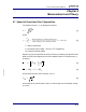
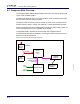
9.3 Composer Elite Overview
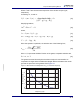
The Composer Elite System Block Diagram (see Figure 9-2) depicts the general
layout of the complete system.
Overall layout depends on the convenient location of the Acoustic Sensor within
the flow of the precursor delivery system.
The Sensor Control Unit may then be located up to 4.6 m (15 ft.) away from the
Acoustic Sensor, either in a relay rack, table top, or deployed within the reactor.
Power is supplied either with the INFICON universal type power supply (option) or
from a user-supplied 24 V (dc) regulated power supply.
Configuration data is provided at set up through the computer link and
Composer Elite Multi-Sensor Software, or through the Sensor Control Unit front
panel control knob and buttons.
Figure 9-2 Composer Elite System block diagram
Mains Power
Optional
Power
Supply
PN 033-0056
24 V(dc)
Sensor
User
Supplied
Computer
Composer Elite
PN 600-1447-P15
Acoustic Sensor
Gas
Gas
Outlet
User
24 V(dc)
Interconnect Cable
Multi-Sensor
Software
Control
Unit
Inlet
4.6 m (15 ft.)