
User guide

1 - 7
PN 074-566-P1B
Composer Elite Operating Manual
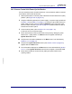
1.4.2 Sensor Control Unit Power-Up Verification
It is not necessary to have Acoustic Sensors or communications cables connected
to the Sensor Control Unit at this time.
1 Set the power switch on the rear panel of the Sensor Control Unit to the 0 (OFF)
position. (See Figure 3-8 on page 3-14.)
2 Using the INFICON (optional) 24 V power supply, or a power supply as defined
in section 1.5.4 and Table 1-1 on page 1-12, insert the output cable of the 24 V
power supply into the connector labeled 150W 24V on the rear panel of the
Sensor Control Unit (see Figure 3-8 on page 3-14). Make certain the cable is
inserted until it locks in place.
3 Connect mains power (refer to section 1.5.4.2 on page 1-12)
to the input of the 24 V power supply.
4 Power up the Sensor Control Unit from the rear panel by setting the power
switch to the 1 (ON) position. The Boot screen will appear followed by a
System Overview screen.
4a Verify that the information displayed on the Boot screen is as described by
section 3.3.2.1 on page 3-5.
4b Verify that the System Overview screen (see section 3.3.2.4 on page 3-8)
appears after the Boot screen.
5 If the information displayed on the Boot screen is not as described by section
3.3.2.1, or if the System Overview screen does not appear, contact INFICON.
6 Power down the Sensor Control Unit by setting the power switch to the
0 (OFF) position.