
User guide

1 - 11
PN 074-566-P1B
Composer Elite Operating Manual
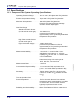
Mounting Requirements . . . . . . . . . . M4-0.7 (4), max. screw penetration 6.4 mm
(0.25 in.) depth threaded holes provided.
Because the attachment to each system
widely varies, a mounting bracket must be
customer fabricated.
Weight . . . . . . . . . . . . . . . . . . . . . . . Approximately 2.3 kg (5.1 lb.)
Storage Temperature Range . . . . . . -10 to +70°C (14 to 158°F)
Humidity Range . . . . . . . . . . . . . . . . 0 to 80% RH non-condensing
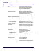
1.5.4 Power Supply
The following sections detail the electrical power specifications for the optional
Power Supply. A universal input power supply converts local mains voltage to
regulated and current limited 24 V(dc) for powering the Sensor Control Unit.
WARNING - Risk Of Electric Shock
Failure to comply with the electrical power requirements
stated below may result in Composer Elite
malfunctioning or being damaged, and could result in
personal bodily injury.
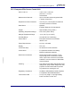
1.5.4.1 Rated Output
Voltage . . . . . . . . . . . . . . . . . . . . . . . 24 V(dc) +5% / -2%
Ripple and Noise . . . . . . . . . . . . . . . 480 mV peak-to-peak max.
Current . . . . . . . . . . . . . . . . . . . . . . . 6.25 A max.
Short Circuit Protection . . . . . . . . . . Continuous, hiccup mode
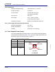
24 V Connector Interface . . . . . . . . . Shielded Cable Assembly
Connector . . . . . . . . . . . . . . . . . . 4-pin, Kycon KPPx-4P or equiv.
Length. . . . . . . . . . . . . . . . . . . . . 1830 mm
Wiring Size . . . . . . . . . . . . . . . . . #14 AWG
+24 V. . . . . . . . . . . . . . . . . Pins 3, 4
Gnd . . . . . . . . . . . . . . . . . . Pins 1, 2
Shield Drain. . . . . . . . . . . . Shell
Shell . . . . . . . . . . . . . . . . . Grounded