
User guide

1 - 12
PN 074-566-P1B
Composer Elite Operating Manual
1.5.4.2 Rated Input
Operational Voltage Range . . . . . . . 100 to 240 V(ac) +/- 10% (ac)
Frequency Range. . . . . . . . . . . . . . . 47 to 63 Hz
In-rush Current . . . . . . . . . . . . . . . . . <60 A at 230 V(ac) input,
25°C ambient cold start
Input Current . . . . . . . . . . . . . . . . . . 2.5 A max.
Overvoltage . . . . . . . . . . . . . . . . . . . 110% - 130% of nominal
(Cycle input power to reset)
Unit Mains Connector. . . . . . . . . . . . IEC320-C14 (Accepts IEC 320-C13)
1.5.4.3 Power Supply Environmental Specifications
Operating Temperature . . . . . . . . . . 0 to +40°C
Storage Temperature . . . . . . . . . . . . -10 to +70°C
Humidity . . . . . . . . . . . . . . . . . . . . . . 20 to 90% non-condensing
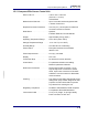
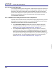
1.5.5 User Supplied Power Supply
If the user provides their own power supply, it must conform to the specifications
and requirements indicated by section 1.5.4. The power supply output cable must
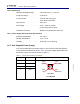
be wired to a 4-pin connector as shown in Table 1-1.
Table 1-1 +24 Volt power connector’s pin diagram
Pin Function Wiring Diagram for Kycon KPPx-45 Plug
1 Gnd
2 Gnd
3 +24 V
4 +24 V
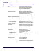
Pin 1
D.W. (GND)
Pin 2
(GND)
Pin 3
White (+V
o
)
D.W. (GND)
Pin 4
(+V
o
)
4 P POWER DIN