
User guide

2 - 6
PN 074-566-P1B
Composer Elite Operating Manual
2.1.3 Composer Elite Location Selection
2.1.3.1 Selecting The Acoustic Sensor Location
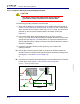
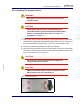
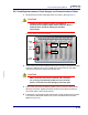
Locate the Acoustic Sensor at a point after the Dilution Flow gas is added and
before the Back Pressure Controller. (See Figure 2-2 on page 2-6.) This creates
the environment with the most stable pressure and flow conditions for best
Composer Elite stability. Positioning the Acoustic Sensor after the Dilution Flow
also simplifies calibration by making it easy to flow pure carrier gas through the
Acoustic Sensor to set the Reference Zero.
Figure 2-2 Basic integration with a reactor
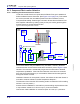
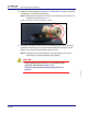
The Acoustic Sensor may be installed in any orientation, however, INFICON
recommends the normal inlet and outlet tube convention (refer to Figure 2-2) be
followed. The inlet tube is substantially longer than the outlet tube to facilitate
temperature equalization. If the inlet and outlet tube connections are reversed,
there may be a small frequency or concentration offset when the total gas flow
through the sensor is varied.
Ventilation clearance is not required; however, the surface the Acoustic Sensor is
mounted to must be at least 5°C below Temperature Setpoint 1.
The dimension from inlet tube VCR-4 sealing surface to outlet tube VCR-4 sealing
surface is 124 mm (4.88 in.).
Acoustic Sensor installation or removal from process tubing requires side-to-side
or top-to-bottom clearance of 152.4 mm (6 in.) for wrench rotation.
Interconnect Cable installation or removal requires 76.2 mm (3 in.) clearance.
Mains
Power
Optional
Power
Supply
24 V(dc)
RS-232
Sensor
Control
Unit
DeviceNet
Interconnect
Cable
Carrier Gas
P
MFC MFC
Bubbler
Dilution Flow
Inlet
Acoustic Sensor
Located downstream
Outlet
Back
Pressure
Controller
Reactor
MFC (Mass Flow Controller)
from Dilution Flow