
User guide

2 - 7
PN 074-566-P1B
Composer Elite Operating Manual
The Interconnect Cable route should be planned to minimize external electrical
interference. (Refer to section 2.1.2.4, Electrical Interference Reduction, on page
2-5.)
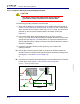
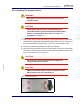
2.1.3.2 Selecting The Sensor Control Unit Location
The Sensor Control Unit is designed for bench top operation or mounting in a
standard 48.26 cm (19 in.) rack using the optional Full Rack Extender
(PN 782-900-007). Ventilation is adequate when operating on a bench top or when
installed in a standard rack using the optional Full Rack Extender.
WARNING
If the Sensor Control Unit will not be mounted in a
standard rack, select a location where the Sensor Control
Unit is protected against falling to prevent instrument
damage and personal injury.
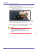
Sensor Control Unit removal from a standard rack requires 30.5 cm (12 in.)
clearance in front of the rack.
Clearance of 7.62 cm (3 in.) is required at the rear of the Sensor Control Unit for
installation or removal of Interconnect, Power Supply, RS-232, and DeviceNet
cables.
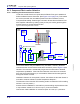
Sensor Control Unit location should be selected to minimize the length of the
grounding strap. (Refer to section 2.1.2.3, Composer Elite System Grounding
Requirement, on page 2-4.)
Interconnect Cable and communication cable routes should be planned to
minimize external electrical interference. (Refer to section 2.1.2.4, Electrical
Interference Reduction, on page 2-5.)